
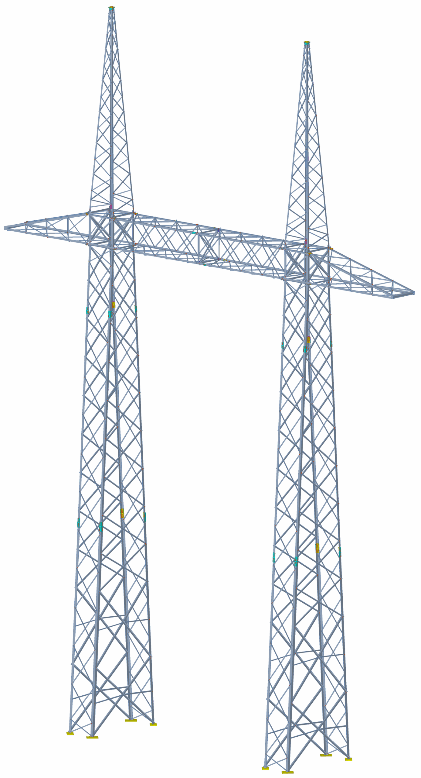
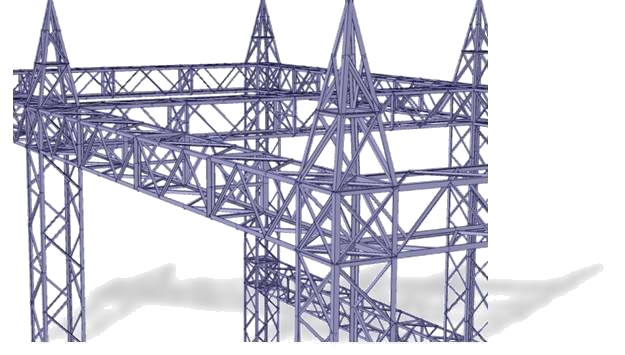
Electrical Substations & Transmission Towers Structural Analysis, Design, Detailing and Fabrication (ASCE)
An end-to-end integrated solution in a single software environment.
Modeling (M) Mode
The modeling phase involves defining the geometry, shape and general parameters of the structural model.
Engineering (E) Mode
The engineering phase involves structural analysis and design carried out by structural engineers in accordance with the applicable codes and standards.
Fabrication (F) Mode
The fabrication phase involves performing fabrication operations on structural components such as cuts, notches, holes, bolting plates, connection design, and welding.
Detailing (D) Mode
The detailing phase involves extracting manufacturing 3D and 2D drawings, engineering drawings, and detail drawings necessary for fabricating components, including those required for CNC (Computer Numerical Control) machine tools.
Come meet VTS's Experts at the
Electrical Transmission & Substation Structures Conference 2025
Booth #815
Dallas, Texas
September 14-18, 2025
Modeling (M) Mode
Les utilisateurs peuvent modéliser des structures avec une interface graphique intuitive alimentée par DirectX 11 et OpenGL 2.0 pour des performances accrues et générer des rapports personnalisables dans Microsoft Word et Excel.
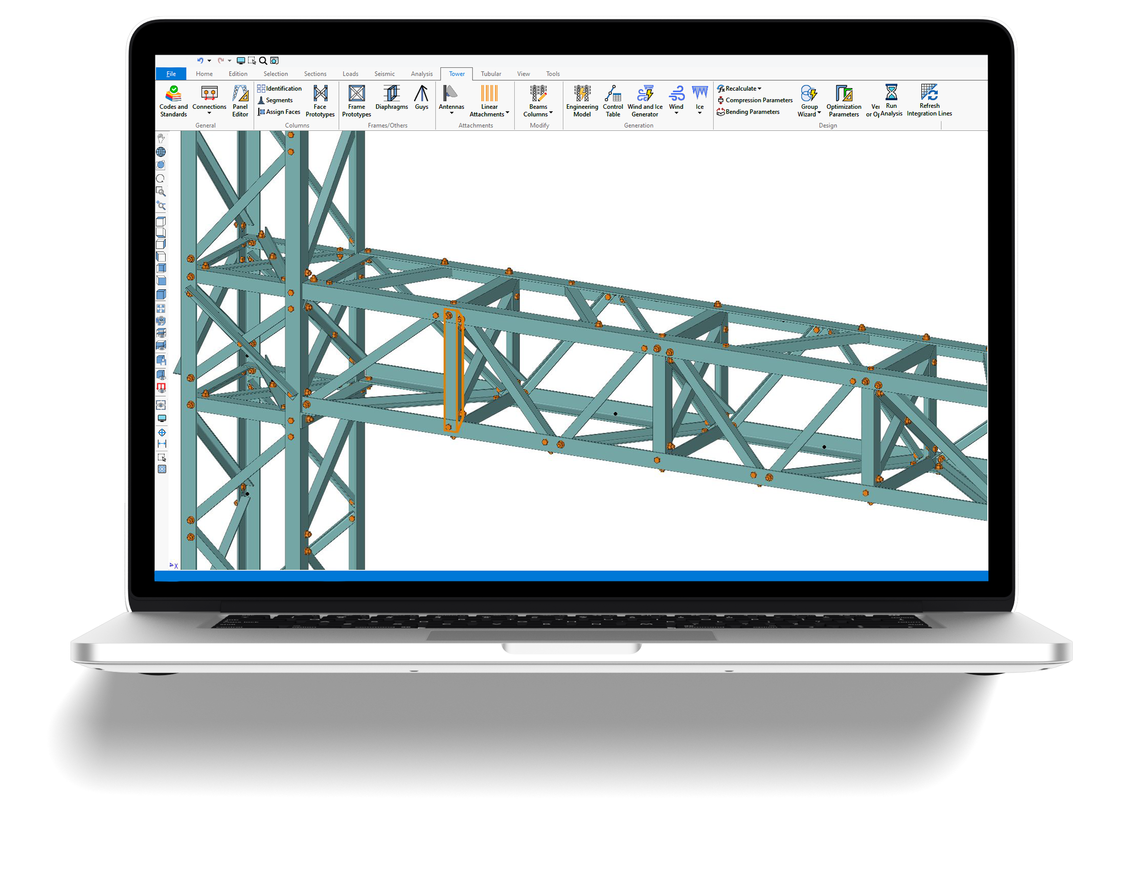
Le logiciel VTS® repose sur une interface en ruban, où les outils et commandes sont organisés par onglets pour une navigation facile. L’interface permet de créer, analyser et concevoir des modèles complexes rapidement. Les modèles peuvent être affichés en lignes, en filaires ou en solides 3D avec des options de transparence pour divers composants.
Manipulez les modèles graphiquement avec une grande flexibilité. L’interface utilisateur en ruban du logiciel VTS® permet de créer, analyser et concevoir rapidement et facilement des modèles complexes. Les modèles peuvent être visualisés sous forme de lignes, de cadres filaires ou rendus en solides 3D. Le programme génère automatiquement des éléments détaillés dans un périmètre de maillage automatique. Une option de transparence est disponible pour divers composants tels que la sélection actuelle, les membres solides, les plaques, les surfaces, les objets spatiaux et les panneaux.

Engineering (E) Mode
Engineering of transmission latticed towers and electrical substations, aligning seamlessly with the ASCE 10-15 standard.
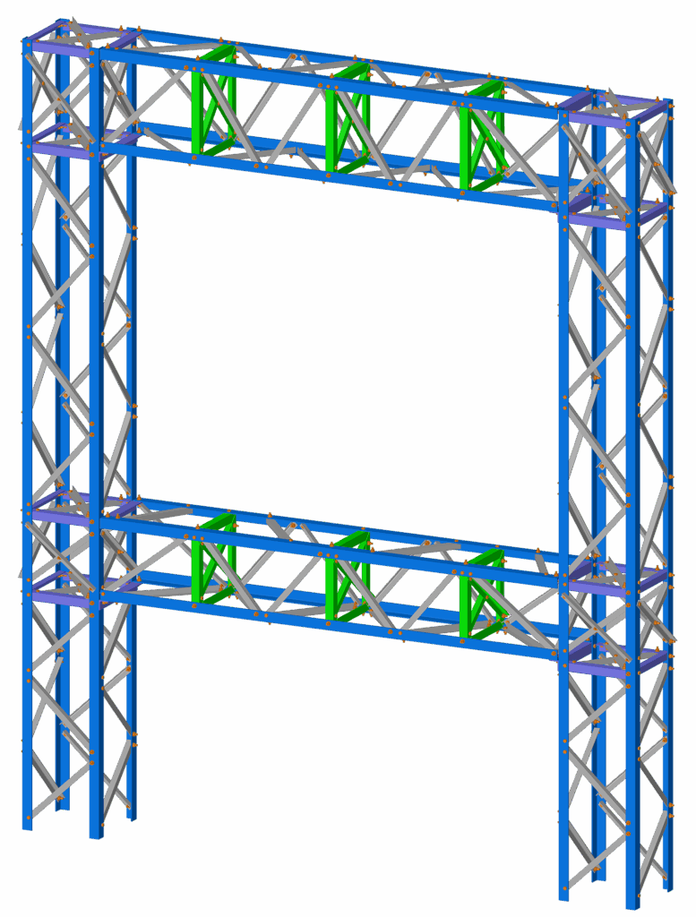
With an expansive library of panel types, VTS® facilitates rapid structure creation through parametric tools. Its automatic generation feature further streamlines the process, offering an extensive repository of panel, rigid connection, and diaphragm prototypes. VTS® stands out by automating the generation of wind and ice loads in accordance with the designated design standard. The results of the analysis and design can be presented numerically or graphically for the entire frame or specific sections, with color-coded charts for visualizing limit states.
The software automatically computes all design and geometric parameters, including slenderness ratios and force coefficients. While these calculations are automated, users also have the flexibility to manually modify them through graphical interfaces or tabular inputs. Additionally, VTS® supports the grouping of members sharing common dimensions and attributes, simplifying manual edits and results interpretation.
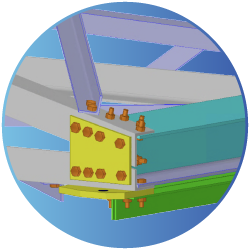
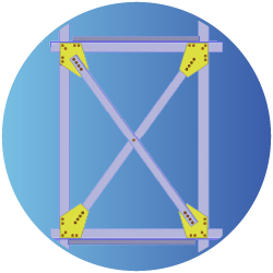
Fabrication (F) Mode
The fabrication phase involves performing fabrication operations on structural components such as cuts, notches, holes, bolting plates, connection design, and welding.
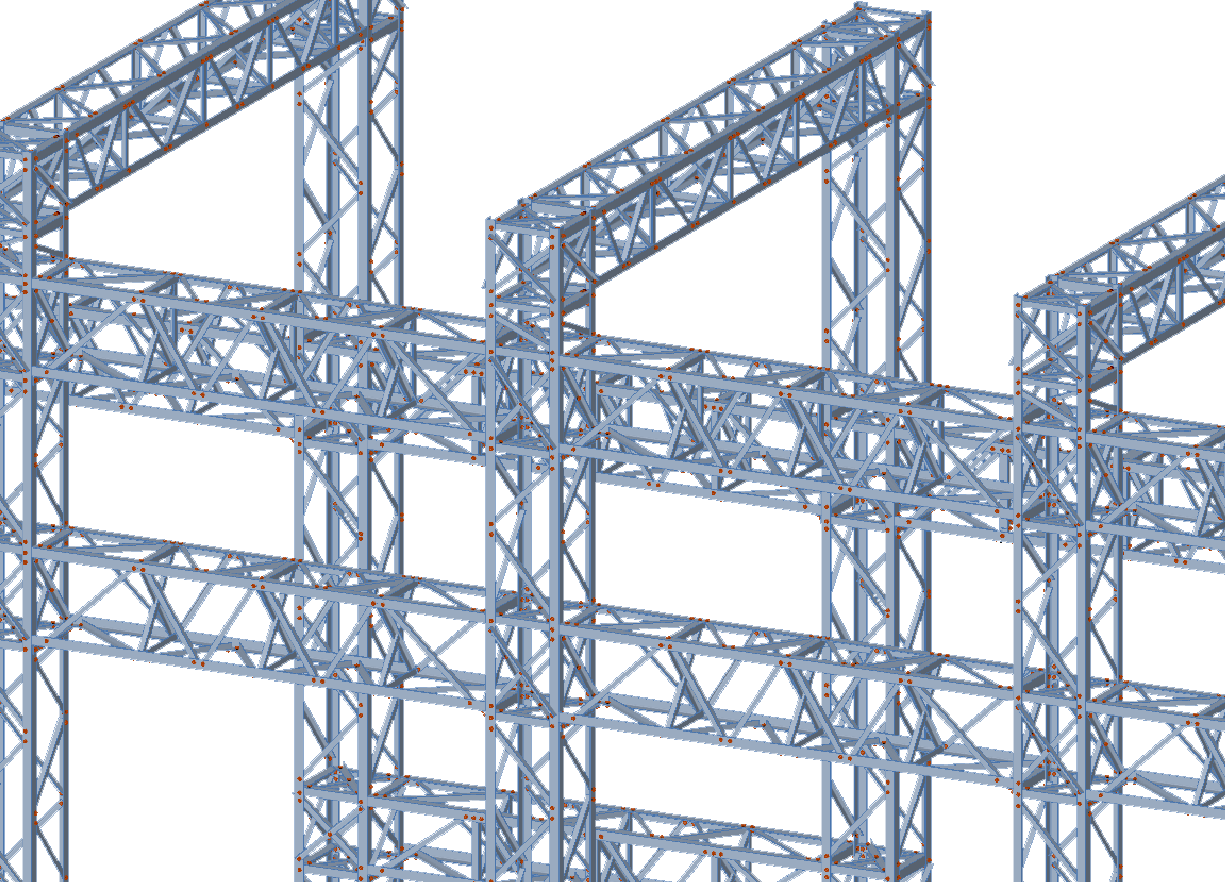
The Fabrication phase uses the structural model directly from Engineering Mode to generate a complete, production-ready fabrication model. VTS® automates detailing for direct bolt connections, splices, base plates, cap plates, gussets, step bolts, and more, minimizing manual work and ensuring accuracy.
Fabrication operations such as cuts, notches, holes, bolting plates, and welds are intelligently applied, with connection designs optimized for real-world manufacturing. Users retain full control to modify details via intuitive graphical or tabular tools.
The result is a fully detailed structure, ready for fabrication output, reducing errors, accelerating delivery, and maintaining full design integrity.
Detailing (D) Mode
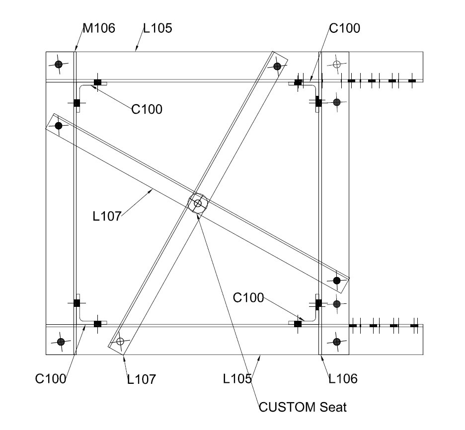
The Detailing phase focuses on generating all required drawings for fabrication, including 2D and 3D manufacturing drawings, engineering drawings, and detail drawings. VTS® extracts these directly from the fabrication model, ensuring consistency and precision across every component.
Editable DWG files and NC (Numerical Control) outputs are created automatically and can be exported directly, ready for CNC machine tools and shop-floor production.
Automatic generation of the fabrication model
including direct bolt connections, splices, base plates, cap plates, step bolts, and gussets
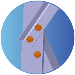
Direct Bolt
Fabrication (F) Mode
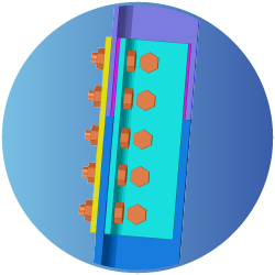
Splice
Fabrication (F) Mode
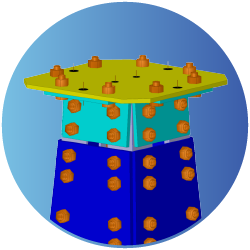
Cap Plate
Fabrication (F) Mode
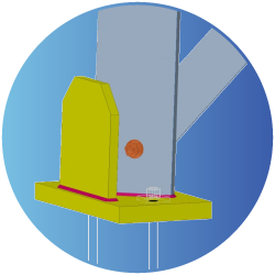
Base Plate
Fabrication (F) Mode
Bloc
Fabrication (F) Mode
Gusset
Fabrication (F) Mode
Request more information
Overview of the VTS® software
Electrical Substations Structural Analysis, Design, Connection Design, Fabrication, Detailing, NC Files
Any questions? Reach out to us today!
Take the next step to discover the VTS Software by completing the following form. One of our experts will get in touch with you shortly. We look forward to assisting you with your inquiries and providing you with the information you need.
Take a quick overview
Lid est laborum dolo rumes fugats untras. Etharums ser quidem rerum facilis dolores nemis omnis fugats vitaes nemo minima rerums

Fugats vitaes nemo minima rerums unsers sadips amets
Virtual Tower Structures®
Text Documentation
Nam libero tempore, cum soluta nobis est eligendi optio cumque nihil impedit quo minus.
Video Documentation
Nam libero tempore, cum soluta nobis est eligendi optio cumque nihil impedit quo minus.
Powerful Interface
Lid est laborum dolo rumes fugats untras. Etharums ser quidem rerum facilis dolores nemis omnis fugats vitaes nemo minima rerums unsers sadips amets. Lid est laborum dolo rumes fugats untras. Etharums ser quidem rerum facilis dolores nemis omnis fugats vitaes nemo minima rerums unsers sadips amets

We Share!
Lid est laborum dolo rumes fugats untras. Etharums ser quidem rerum facilis dolores nemi rumes rerum facilis.

We Care!
Lid est laborum dolo rumes fugats untras. Etharums ser quidem rerum facilis dolores nemi rumes rerum facilis.

Virtual Tower Structures®
VTS = M + E + F + D
Virtual Tower Structures® (VTS) is a robust Microsoft Windows application tailored for the comprehensive analysis, design, connection design, fabrication and detailing of electrical substations and steel transmission structures.
The VTS® software is a technology built on a ribbon-based interface, offering a streamlined design element where tools, commands, and options are conveniently organized into tabs and groups for effortless access and navigation.
The VTS® software is robust tool developed by SAFI Structural Software. Established in 1986, SAFI is a technology-driven company designed to empower engineers to tackle complex structural challenges with ease. With a rich history of 38 years of continuous development, the VTS® software stands as an example of innovation in the electrical utility industry.
Modeling (M) Mode
Engineering (E) Mode

Fabrication (F) Mode
Detailing (D) Mode
Fonctionnalités intuitives de modélisation
L’interface graphique du logiciel VTS® permet de créer, analyser et concevoir rapidement et facilement des modèles complexes. Les modèles peuvent être affichés sous forme de lignes, de cadres filaires ou rendus en solides 3D. Les fonctionnalités du programme VTS® permettent de générer automatiquement des éléments détaillés dans un maillage généré automatiquement. Une option de transparence est disponible pour divers composants tels que la sélection actuelle, les membres solides, les plaques, les surfaces, les objets spatiaux et les panneaux.
Systèmes d’unités
Les systèmes d’unités métriques, impériaux et mixtes sont autorisés et peuvent être modifiés à tout moment. Les rapports peuvent être imprimés selon n’importe quel système d’unités.
Manipulez les modèles graphiquement avec une grande flexibilité.
Le logiciel VTS® comprend des fonctionnalités puissantes et productives pour générer tout type de modèles :
– Systèmes de coordonnées locaux
– Lignes de construction linéaires ou circulaires pour créer des modèles
– Commandes automatisées pour déplacer, tourner, extruder, copier, attacher, subdiviser, etc.
– Modèles modifiables graphiquement ou via des tableaux
– Outils d’édition puissants et génération automatique
– Sélection graphique d’éléments ou selon des critères
– Groupes persistants d’objets sélectionnés
– Attributs des éléments modifiables graphiquement ou via des tableaux (sections, paramètres d’analyse, angles de rotation, etc.)
– Surfaces utilisées pour le transfert de charges et calcul du poids propre.
Fonctionnalités d'affichage
Le programme VTS adapte la taille des images pour une interface facile à utiliser, même sur des écrans à très haute résolution. Il propose une visualisation 3D ultra-rapide en modes filaire ou solide, avec un affichage personnalisé des objets graphiques et une visualisation partielle des modèles. Les résultats peuvent être affichés pour l’ensemble ou une partie de la structure, individuellement ou par groupe, via des graphiques et des tableaux numériques. Les résultats d’analyses sismiques et dynamiques peuvent également être visualisés graphiquement. La taille des modèles est limitée par la capacité physique de l’ordinateur.
Objects transparency for various components such as current selection, solid members, plates, surfaces, spatial objects, panels. The level of transparency may be customized for each type of object from the Display Options command.
Functionalities of the VTS® program allow to generate automatically detail elements in an automatically generated mesh perimeter. These functionalities are specifically related to the refinement area, the opening, the linear constraint and the punctual constraint.
All detail elements added to the VTS® model will be automatically connected to the finite element mesh. The mesh perimeter will also connect any elements already in the model to the mesh perimeter automatically if they are in the plane of the mesh contour.
Engineering (E) Mode
The engineering phase involves structural analysis and design carried out by structural engineers in accordance with the applicable codes and standards.
The Virtual Tower Structures® (VTS) software provides a powerful and flexible platform for structural engineers to streamline their design workflows and optimize design time. The VTS® software is specifically built to suit your tower workflow and optimize design time. With both graphical and numerical table definition of tower structures, you can design and complete projects faster than ever.
By integrating various design and analysis tools, VTS® aims to help engineers optimize their design time. This efficiency is critical in today’s fast-paced engineering projects, allowing for quicker turnaround times and cost-effective designs.
Highlighted Features
Custom Reports & Report Presets
VTS® has the flexibility to generate customized reports tailored to users’ precise requirements. This feature allows the creation of concise custom reports containing only essential information, thereby minimizing report size. Additionally, users can establish predefined report templates and save report layout templates for convenient reuse in other files.
Create realistic Graphics
VTS® boasts a user-friendly interface, a robust analysis engine, comprehensive design checks, and advanced visualization tools, rendering the modeling of complex towers a seamless process. With a modern graphical user interface, users can effortlessly achieve realistic visualizations of their models. Additionally, powerful edition features allow to model very complex and non-standards towers.
Design new and existing towers
The design capabilities within VTS® offer an outstanding solution for both creating new towers and assessing existing structures when subjected to modified loads.
Reliable Structural Analysis Capabilities You Can Trust
The VTS® software features comprehensive state-of-the-art structural analysis methods, including:
FEA Finite Elements Analysis, Static Analysis, Linear and Nonlinear Analysis, P-Delta Analysis, Natural Frequency Analysis, Static Equivalent Seismic Analysis, Dynamic Time-History Analysis, Seismic Time-History Analysis, Modal Analysis, Spatial Objects and Spatial Loads, Buckling Analysis, Response Spectrum Analysis, Advanced Section Stress Analysis, Torsion and Warping, Built Up Sections, Catenary Cables, Nonlinear springs, Diaphragm Analysis, Horizontal Notional Loads, Loads and Load Combinations.
State-of-the-art analysis tools
FEA including plates and shell elements
Torsion including restrained warping of open sections
Linear and exact non-linear cable elements (catenary cables)
Non-linear analysis using load control and displacement control strategy for better convergence
Possibility to add non-structural components using spatial objects
Design checks of sections according to the AISC 360 and CSA S16 standards.
Possibility to add non-structural components using spatial objects to automatically calculate dead, ice, and wind loads
Automatic handling of unidirectional elements such as tension-only members
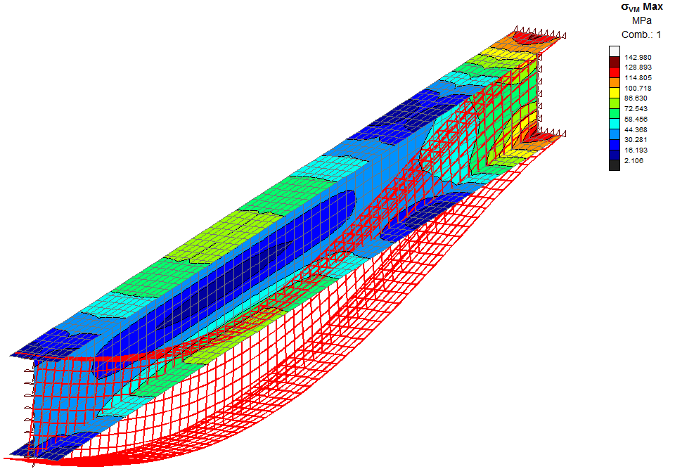
Gain deeper insights into structural behavior
The VTS® software enables users to animate results from various analyses, including static linear, P-Delta, buckling, natural frequencies, seismic, and dynamic analysis. This feature helps visualize structure displacements, internal forces, stresses, support reactions, mode shapes, and time-history data, providing a clearer understanding of structural behavior during different events.
Gain deeper insights into structural behavior during dynamic events, such as identifying the critical moments of dynamic loading. Animating the envelopes streamlines the information displayed, allowing users to focus on the model’s most critical regions.
Offering advanced features for result animation
Custom Executive Report
VTS® software provides an exhaustive set of result features that include graphical views, diagrams, numerical tables, and text reports.
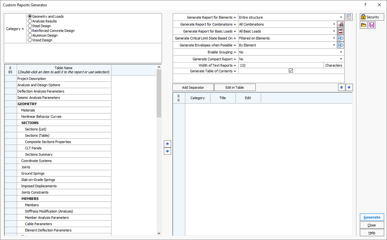
Benefit from Custom Reports capabilities to easily create tailored reports with editable content selection and arrangement. Take advantage of predefined templates and save your custom layouts for efficient use in future projects.
Advanced Reporting Feature:
· Select data types based on the application and modules used.
· Seamlessly add individual or multiple tables to the report from the selected group.
· Customize report settings that apply to the entire document, with the flexibility to override options for specific tables.
· Manage report layout with custom titles, table edits, and reorder tables using intuitive controls.
Generate the report for the whole model or a selection of elements.
Printing limit states results for the critical results only for each member or for physical member for the critical combination.