Highway Sign Structures Analysis, Design and Evaluation Software
- 39 years of Canadian Innovation
A state-of-the-art solution specifically designed for Departments of Transportation (DOTs) and engineering firms across the United States.

A state-of-the-art solution specifically designed for Departments of Transportation (DOTs) and engineering firms across the United States.

HSE™ structural software is an automated structural program for modeling, analysis, design and evaluation of latticed Highway Sign Structures, Overhead Sign Structures, Gantry structures, Cantilevers, Traffic Signals and High-Mast Lighting Towers (HMLT).
The program supports the required specifications of the AASHTO LTS-13 ASD (6th edition), AASHTO LTS-15 LRFD (1st edition), CAN/CSA S6.
This 3D frame analysis software offers intuitive modeling features, comprehensive structural analysis capabilities and powerful design tools. The HSE™ software is user-friendly, easy-to-use and built on a ribbon-based interface, offering a streamlined design element where tools, commands, and options are conveniently organized into tabs and groups for effortless access and navigation.


HSE™ software enables users to design a wide range of traffic signal and mast arm structures. It accounts for truck-induced gust loads and galloping forces by evaluating the frontal projected area of each traffic signal.
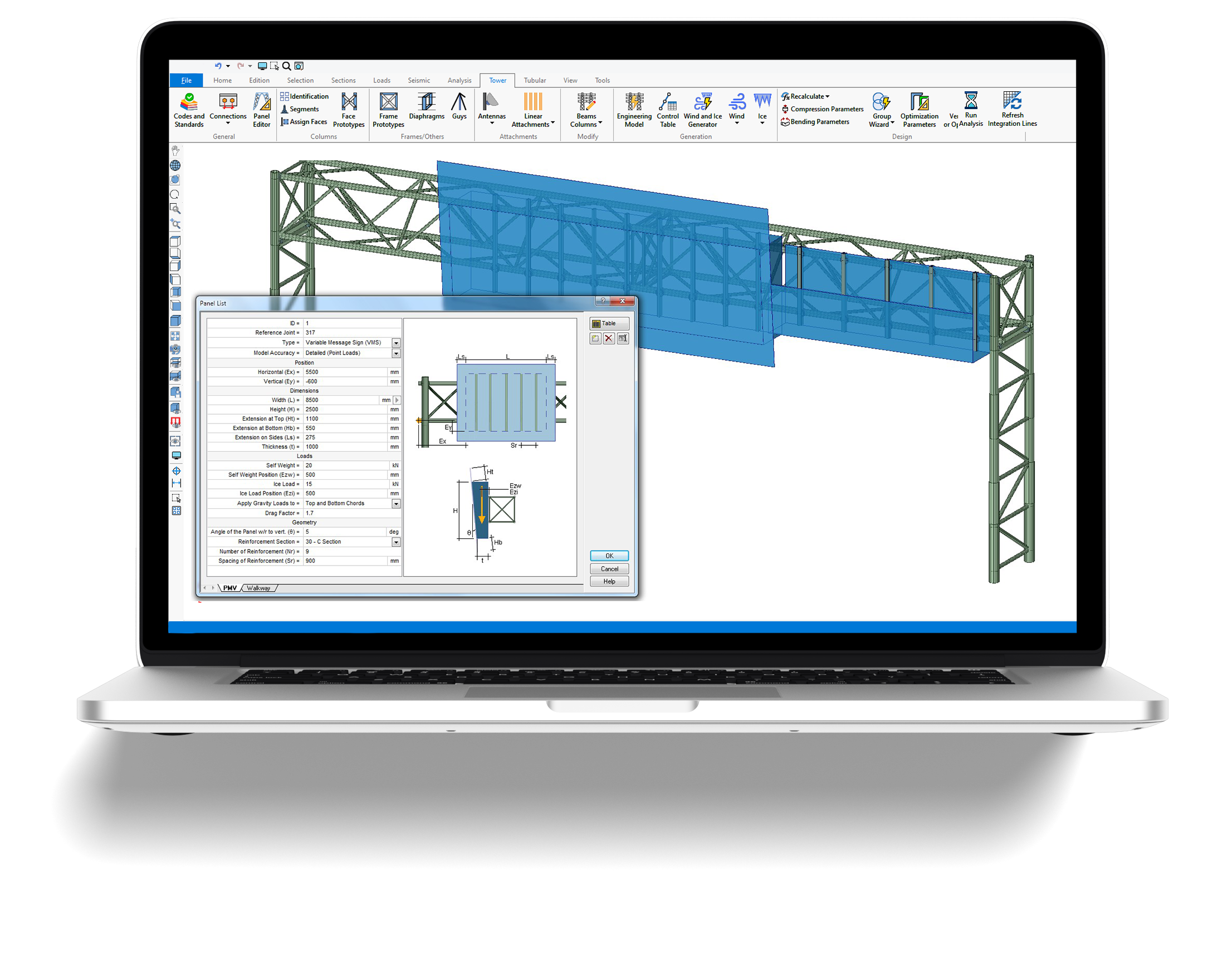
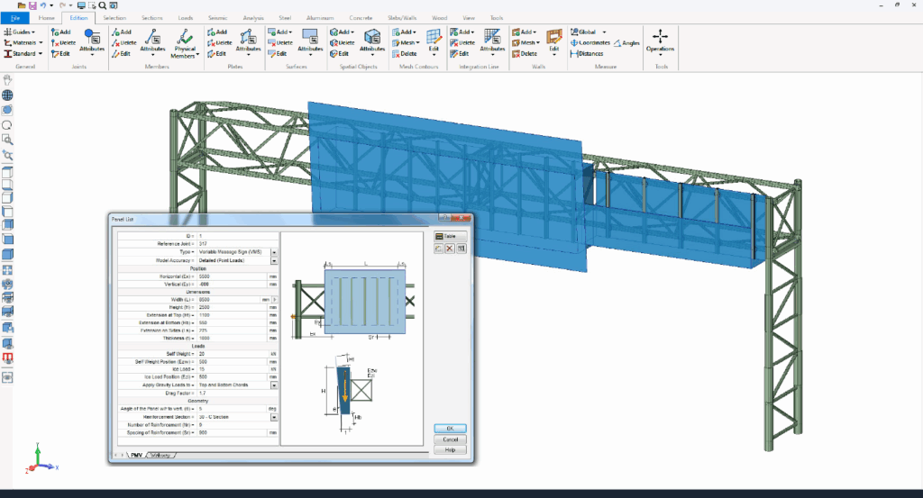
The software also supports the design of overhead sign structures featuring various types of road sign panels, including simple panels, reinforced panels, variable message signs (VMS), walkways, and secondary panels. It automatically calculates wind, ice, and gravity loads for these configurations.
In addition, HSE™ allows users to design diverse lighting structures such as streetlight poles, high-mast towers, and lamp posts. The program factors in natural wind gusts that can generate cyclic loads on these lighting systems.


HSE™ Structural Software provides a powerful and flexible platform for structural engineers to streamline their design workflows and optimize design time. With over a dozen of automated structural models, HSE™ software empowers users to effortlessly create various types of structures such as:
Additionally, HSE™ software offers a manual mode for designing various structures, such as high-mast lighting towers, traffic signal signs, and more.
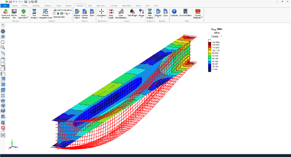
The HSE™ software features comprehensive state-of-the-art structural analysis methods, including:
• Finite Elements Analysis (FEA) including plates and shell elements
• P-Delta Analysis, Linear and Nonlinear Analysis, Buckling Analysis
• Static Equivalent Seismic Analysis, Seismic and Dynamic Time-History Analysis
• Non-linear analysis using load control and displacement control strategy
• Non-linear springs
• Torsion including restrained warping of open sections
• Linear and exact non-linear cable elements
• Direct Analysis Method (DAM) and the Effective Length Method (kL) for AISC 360
• Frequency and Response Spectrum Analysis
• Possibility to add non-structural components using Spatial Objects and Spatial Loads
• Advanced Section Stress Analysis and Built-up sections, and more analysis features
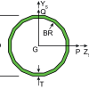
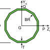
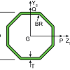
In addition to all existing section shapes (circular, rectangular, I, L, 2L, T, and more), HSE™ Highway Sign Structural Engineering software allows the use of tubular polygonal sections.
• 18-sided tube
• 16-sided tube
• 12-sided tube
• 8-sided tube
• 6-sided tube


HSE™ software allows users to animate analysis results, including static, P-Delta, buckling, seismic, and dynamic analyses. This visualization highlights displacements, internal forces, stresses, reactions, mode shapes, and time-history data, offering clear insights into structural behavior.
Animating envelopes focuses on critical regions, simplifying complex data for better decision-making during dynamic events.
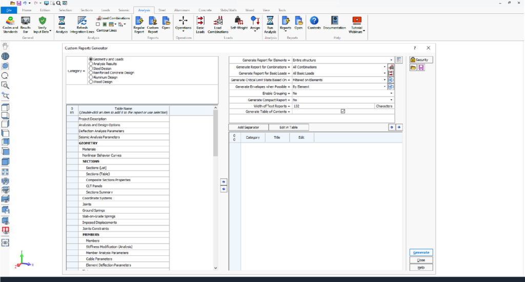
HSE™ software offers advanced custom reporting tools, enabling users to create tailored, professional reports with ease. With options to select relevant data, add individual or multiple tables, and customize settings, users can design layouts that meet specific project needs.
Editable titles, table reordering, and predefined templates enhance efficiency, while saved custom layouts streamline future reporting. Reports can be customized and exported to Microsoft Word and Excel, streamlining workflows.
HSE™ software features an intuitive, ribbon-based graphical user interface powered by DirectX 11 and OpenGL 2.0 for enhanced performance. Users can efficiently create, analyze, and design complex models, visualized as lines, wireframes, or 3D solids.
Users benefit from key functionalities such as automated mesh generation, detailed element creation, and transparency options for components like members, plates, surfaces, spatial objects and panels.
The software supports metric, imperial, and mixed unit systems, which can be modified at any time.
HSE™ software offers versatile modeling tools to create any type of structure efficiently. Key features include local coordinate systems, linear or circular construction lines, and automated commands like move, rotate, extrude, and subdivide.
Models can be edited graphically or via spreadsheets, with options for batch or individual element creation. Persistent groups, advanced selection tools, and renumbering options enhance productivity. Attributes can be set graphically or in spreadsheets, and surfaces facilitate load transfer and self-weight calculations.
Results and input data can be visualized, printed, and exported with flexible options for customization, reporting formats, and graphics sharing.
• Visualize results graphically or numerically.
• Print input data and results for the entire structure or specific parts using graphical selection or element ranges.
• Customize lists of input data and results for printing.
• Reports available in multiple formats: SAFI™ reports, Excel, Access, and ASCII text files.
• Graphics can be printed or copied to the clipboard for use in other programs.
Explore the extensive features and functionalities of HSE™ Highway Sign Structural Engineering software.
HSE™ Software
Structural Modeling, Analysis, Design and Evaluation software
Our team is here to assist with any inquiries—whether you're exploring options, scheduling a demo, requesting pricing, or seeking help to get started with the HSE™ software.
Take the next step to discover HSE™ Software by completing the following form. One of our experts will get in touch with you shortly. We look forward to assisting you with your inquiries and providing you with the information you need.
• The HSE Structural Software is an automated program designed for:
-Latticed Highway Sign Structures
-Overhead Sign Structures
-Gantry structures
-Cantilevers
-Traffic Signals
-Luminaire Support Structures
-High-Mast Lighting Towers (HMLT)
• The HSE software utilizes high-end parametric technology for generating and designing various Sign Structures.
• It provides powerful features for creating diverse latticed structural models.
• Automated tools within the software determine wind and ice loads, along with other relevant design parameters like slenderness ratios and drag coefficients.
• The HSE is a robust and reliable structural software built on over 38 years of Research and Development.
• Designed with the latest technological innovations, it features a sophisticated and user-friendly graphical ribbon-based interface.
• This engineering software solution is globally utilized by several notable international companies in production work for building innovative sign structures.
• The HSE program calculates the resistance and various design parameters of all elements within a Highway Sign Structures model.
• It adheres to Canadian, American, and European Steel codes, supporting specifications such as:
– AASHTO LTS-13 ASD (6th edition)
– AASHTO LTS-15 LRFD (1st edition)
– AISC 360-10 LRFD
• Additionally, the program supports American Aluminum AA ADM-2015 (LRFD) and Aluminum AA ADM-2015 (ASD) for general structures, as well as Canadian aluminum codes CAN/CSA-S157.
• The HSE Structural Software supports ice loads and wind loads, which can be defined according to various distribution methods.
• Distribution methods range from uniform distribution and user-defined distributions to sophisticated methods like those proposed in the IEC-826 document.
• Ice loads and wind loads are automatically distributed to both the latticed structure and the sign panels.
• AASHTO LTS-13 ASD (6th edition)
• AASHTO LTS-15 LRFD (1st edition)
• Canadian CSA S6
• Structure design for compression, tension, shear, bending, slenderness, torsion and warping, fatigue, and deflection
• Anchor rods verification
• Base plate design and verification
• Automated self-weight
• Automated wind and ice loads
• Concentrated and distributed loads
• Automated fatigue
• Thermal gradient loads
• Seismic analysis capabilities
• Automated load combinations
• The HSE software includes the fatigue limit states.
• Fatigue verification according to chapter 11 of AASHTO LTS-13 (ASD) and AASHTO LTS-15 (LRFD)
• Verification of stresses according to the Constant Amplitude Fatigue Threshold (CAFT)
• The CAFT (Constant Amplitude Fatigue Threshold) or BIFAT (for infinite life for the different fatigue detail categories) are found in AASHTO LTS-13 (ASD) and AASHTO LTS-15 (LRFD)
• Based on the requirements, fatigue verifications such as Galloping, Natural Wind Gust, and Truck-Induced Gust can be selectively activated
• Applicable fatigue loads must be specified according to the structure type, as mandated by the AASHTO LTS code requirements
The HSE software allows users to create different types of structures automatically:
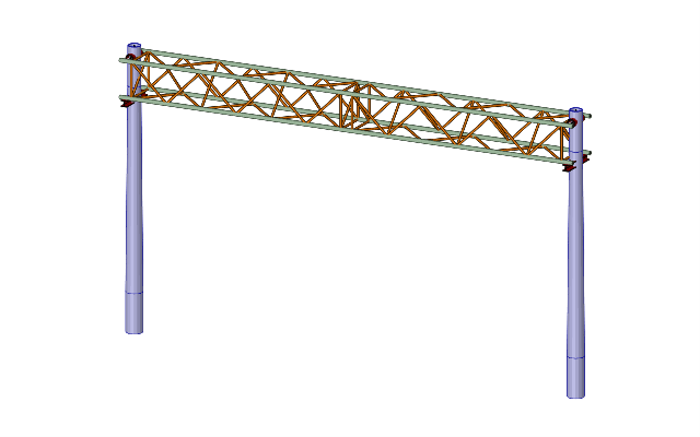
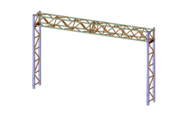
• 2 or 3 latticed columns with 4-sided latticed beam
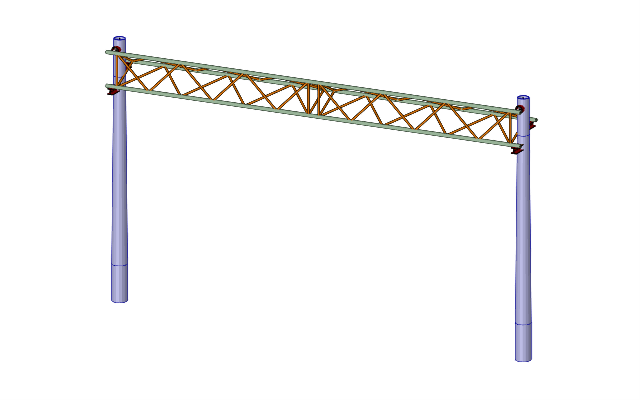
• 2 or 3 latticed columns with 3-sided latticed beam
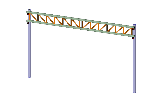
• 2 or 3 pole columns with 4-sided latticed beam
• 2 or 3 pole columns with flat latticed beam
• 1 pole column with 4-sided cantilever arm
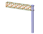
• 2 pole columns with tubular beam
• 1 latticed column with cantilever tubular arms
• 1 pole column with cantilever tubular arms
• 1 pole column with cantilever flat latticed arm
• Monopole generator
Users also have the option to manually construct models, enabling the creation of diverse structures such as:
• High mast lighting towers
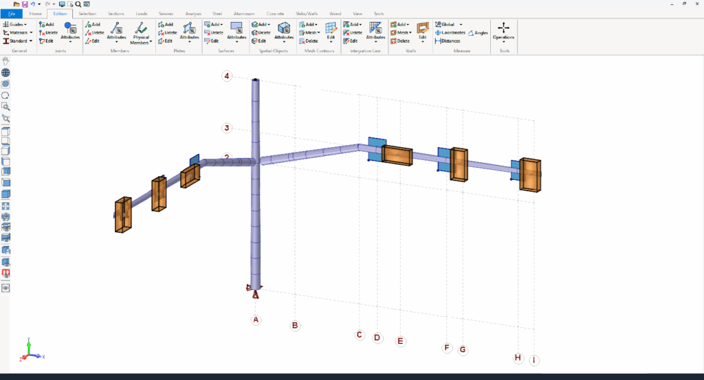
• Multiple signal roadside signs
• Other customizable structures
In addition to all the existing section shapes (circular, rectangular, L, I, Z, T…), the tubular polygonal sections are also available:
• 18-sided tube
• 16-sided tube
• 12-sided tube
• 8-sided tube
• 6-sided tube
• Multiple features for beam generation available to HSE users.
• Users can select from different panel models for beam diagonals.
– Warren
– Pratt
– Pony Warren
– Pratt
• Option to reverse the panel models using the “Discontinuous Diagonals” option.
• Option to align diagonals on the opposite face of the beam when “Invert opposite face” is unchecked.
• Ability to specify different panel models for:
– Vertical faces of the beam
– Horizontal faces of the beam
• By default, horizontal panels are identical to vertical panels.
• Various options provided for the interior diagonals, such as:
At ends only
By default, the interior diagonals are repeated at each panel. When this option is checked, the diagonals are generated only at the segment ends.
Offset (Δd)
The first and last interior diagonal of a segment can be offset toward the inside of the beam by a distance of Δd.
• The HSE software also allows automatically generating beams made of single angle sections.
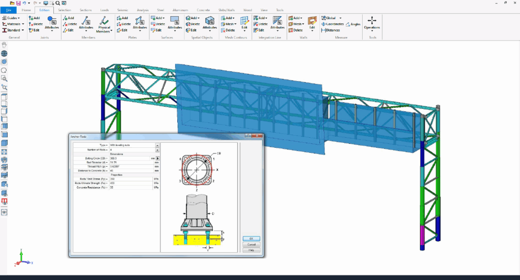
• The HSE software allows computation of the resistance and/or the thickness of base plates with leveling nuts.
• Base plate design and verification.
• Anchor rods verification.
Anchor rods
• The “Highway Sign Anchorages” command allows defining the input data for the anchorages.
• Anchorage resistances and limit states are computed according to clauses specified in the selected standard:
– AASHTO LTS-15 (LRFD) clause 5.16.3
– AASHTO LTS-13 (ASD) clauses 5.17.4.1 to 5.17.4.3
• Fatigue verification for anchorage rods is computed based on the specified allowable stress range (DF)ₜₕ.
• The HSE software offers comprehensive structural analysis methods, including:
FEA Finite Elements Analysis, Static Analysis, Linear and Nonlinear Analysis, P-Delta Analysis, Natural Frequency Analysis, Static Equivalent Seismic Analysis, Dynamic Time-History Analysis, Seismic Time-History Analysis, Modal Analysis, Spatial Objects and Spatial Loads, Buckling Analysis, Response Spectrum Analysis, Advanced Section Stress Analysis, Torsion and Warping, Built Up Sections, Catenary Cables, Nonlinear Springs, Diaphragm Analysis, Horizontal Notional Loads, Loads and Load Combinations.
State-of-the-art Analysis Tools
FEA including plates and shell elements
Torsion including restrained warping of open sections
Linear and exact non-linear cable elements (catenary cables)
Non-linear analysis using load control and displacement control strategy for better convergence
Possibility to add non-structural components using spatial objects
Complying with Seismic Requirements
Seismic response spectrum, seismic time-history, and dynamic time-history analysis
Customized response spectrums and accelerograms
Fully customizable analysis parameters
Maximal response using CQC and SRSS methods
Automated or user-defined damping
Graphical display of response spectrums and accelerograms
User-defined incidence angle of seismic loads and vertical components
Customized analysis and output time steps
Time-history results can be provided for selected parts of the models
• The Redesign feature allows to test different solutions without requiring to run the analysis each time.
• Calculation of Compression, Tension, Bending, Compression-Bending, Tension-Bending, Shear, Torsion and Warping, Slenderness based on the results of a Linear, P-Delta and Non-Linear analysis, Seismic Static, Seismic Spectral and Dynamic analysis.
• Simply symmetric, asymmetric and built-up section shapes are covered for all design codes.
• Classification, resistance and stability computations performed according to the specified aluminum standard.
• The program distinguishes two types of welds: End welds and In-span welds.
• Each of these types of welds may be full (affecting the entire cross section) or partial (affecting a portion of the cross section).
• Calculation of combined resistance of aluminum elements based on the results of a linear, P-Delta, non-linear, seismic or dynamic analysis.
• All parameters required to calculate the resistance of the elements, such as unbraced lengths, buckling lengths, buckling factors, welding, slenderness limit, and others, can be customized either graphically or from spreadsheets.
• Displayed graphically on the 3D model through color representation or presented numerically in spreadsheets and reports
• Customizable, user-friendly, and exhaustive report generation in multiple formats including Word document and Excel worksheet
• Generate executive report summary by printing the results for only the critical load combination