Multi-Material Structural Analysis and Design software for Timber, CLT, Light-Frame Wood, Steel, Cold-Formed Steel, Reinforced Concrete, Slab & Foundation design and Aluminum.
Trusted by the world's leading engineering firms for over
40 years
Delivering cutting-edge solutions to industry leaders since 1986.
Engineered for productivity. Built exclusively for structural engineers.
GSE™ is built for multi-material structural analysis and design — Timber, Steel, Cold-Formed Steel, Concrete, Slab and Aluminum.
Multi-material modeling - Unified in one environment
Steel, Timber, Concrete, and Aluminum within a single model — multi-material design and analysis simultaneously within a single, unified platform.
Comprehensive structural analysis - with animated results
Full analysis capabilities including Static, P-Delta, Non-linear, Buckling, Seismic, and Dynamic Time-History — with animated results and interactive result tables.
Powerful design tools - Built for productivity
Redesign optimization, automated load combinations, slab generators, and custom executive reports — purpose-built for structural engineering workflows.
A productive software built for structural engineers.
GSE™ Software – Explore the various features and workflow in a short technical walkthrough.
Register today to receive your free demo video directly in your inbox.
Core features of GSE™ Structural Software
A structural analysis and design software for professional engineers.
Integrated design standards
The GSE™ software offers an integrated, flexible platform for structural engineers, streamlining workflows and optimizing design time with simultaneous multi-material design capabilities.
• Seismic design requirements for buildings as per ASCE, NBCC 2020 • Live load reduction factor (LLRF) for NBCC, ASCE • Integrated load combinations from ASCE, NBCC, ULS, SLS, Fatigue, Fire resistance • Timber and wood design as per National Design Specification (NDS), CSA O86 • Reinforced concrete member design as per ACI-318, CSA-A23.3, EC2, ECP-203 • Steel member design for AISC 360 LRFD & ASD, CSA S16, Eurocode 3 and 4, IS 800 • Cold formed steel for AISI S100 and S136 • Aluminum design for AA ADM and CSA S157
Robust and comprehensive structural analysis
GSE™ delivers advanced structural capabilities with a complete spectrum of analysis types including:
• Finite Elements Analysis (FEA) including plates and shell elements
• P-Delta Analysis, Linear and Nonlinear Analysis, Buckling Analysis
• Static Equivalent Seismic Analysis, Seismic and Dynamic Time-History Analysis
• Non-linear analysis using load control and displacement control strategy
• Non-linear springs
• Torsion including restrained warping of open sections
• Linear and exact non-linear cable elements
• Direct Analysis Method (DAM) and the Effective Length Method (kL) for AISC 360
• Frequency and Response Spectrum Analysis
• Possibility to add non-structural components using Spatial Objects and Spatial Loads
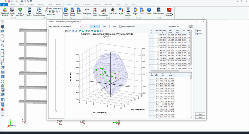
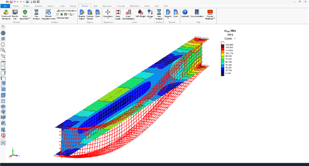
• Advanced Section Stress Analysis and Built-up sections, and more analysis features
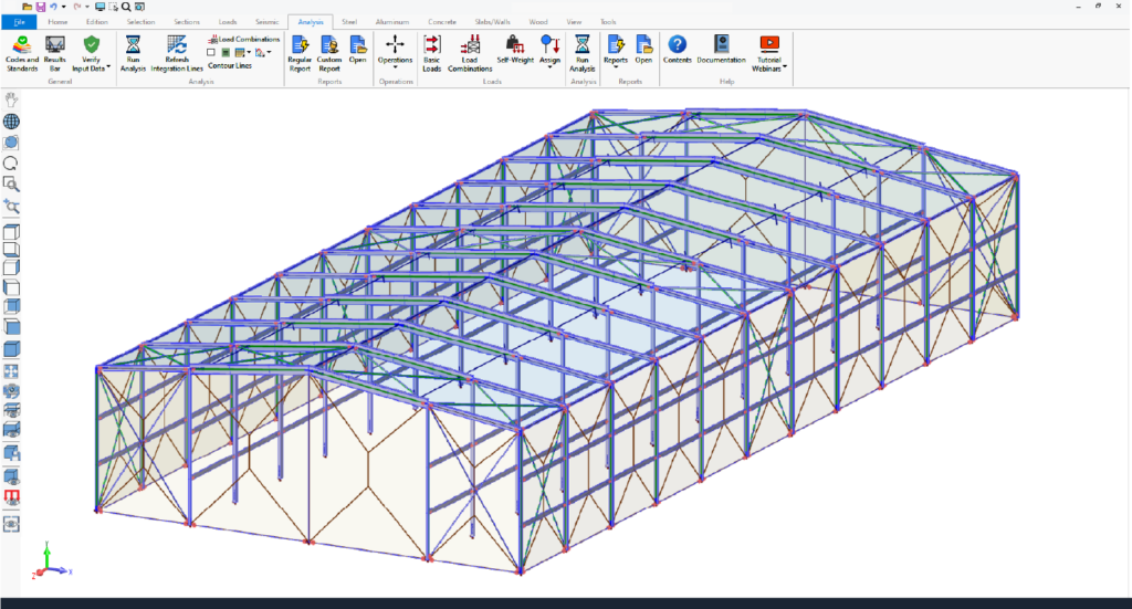
Structural insights animation
GSE™ software allows users to animate analysis results, including static, P-Delta, buckling, seismic, and dynamic analyses. This visualization highlights displacements, internal forces, stresses, reactions, mode shapes, and time-history data, offering clear insights into structural behavior.
Animating envelopes focuses on critical regions, simplifying complex data for better decision-making during dynamic events.
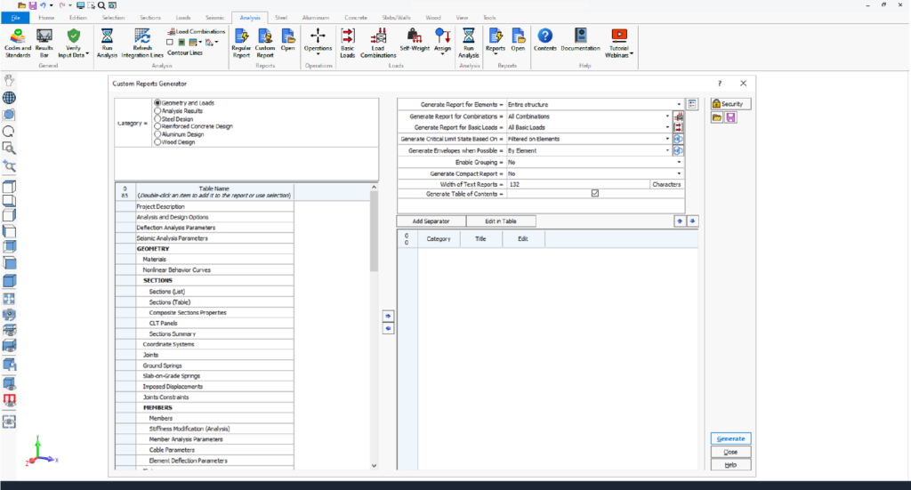
Executive custom reporting - editable professional reports
GSE™ software offers advanced custom reporting tools, enabling users to create tailored, professional reports with ease. With options to select relevant data, add individual or multiple tables, and customize settings, users can design layouts that meet specific project needs.
Editable titles, table reordering, and predefined templates enhance efficiency, while saved custom layouts streamline future reporting. Reports can be customized and exported to Microsoft Word and Excel, streamlining workflows.
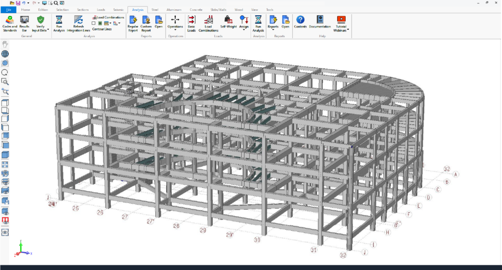
Intuitive graphical ribbon-based interface
GSE™ software features an intuitive, ribbon-based graphical user interface powered by DirectX 11 and OpenGL 2.0 for enhanced performance. Users can efficiently create, analyze, and design complex models, visualized as lines, wireframes, or 3D solids.
Users benefit from key functionalities such as automated mesh generation, detailed element creation, and transparency options for components like members, plates, surfaces, spatial objects and panels.
The software supports metric, imperial, and mixed unit systems, which can be modified at any time.
Efficient modeling tools
GSE™ software offers versatile modeling tools to create any type of structure efficiently. Key features include local coordinate systems, linear or circular construction lines, and automated commands like move, rotate, extrude, and subdivide.
Models can be edited graphically or via spreadsheets, with options for batch or individual element creation. Persistent groups, advanced selection tools, and renumbering options enhance productivity. Attributes can be set graphically or in spreadsheets, and surfaces facilitate load transfer and self-weight calculations.
Comprehensive results visualization
Results and input data can be visualized, printed, and exported with flexible options for customization, reporting formats, and graphics sharing.
• Visualize results graphically or numerically.
• Print input data and results for the entire structure or specific parts using graphical selection or element ranges.
• Customize lists of input data and results for printing.
• Reports available in multiple formats: SAFI™ reports, Excel, Access, and ASCII text files.
• Graphics can be printed or copied to the clipboard for use in other programs.
Enhanced Multi-Material design for Steel, Concrete, Timber and Aluminum
within a single, integrated software environment
Combine Steel, Concrete, Timber, CLT, Cold-Formed Steel, and Aluminum within a single structural model — with full code-checking for each material simultaneously.
GSE™ Timber Module
CLT, Mass Timber, and Light-Frame Wood design per NDS and CSA O86 — including shear wall generation, custom lay-ups, and orthotropic CLT behavior.
Reinforced concrete, slab, and foundation design per ACI-318, CSA-A23.3 and ECP-203 — including punching shear, design strips, and slab-on-grade analysis.