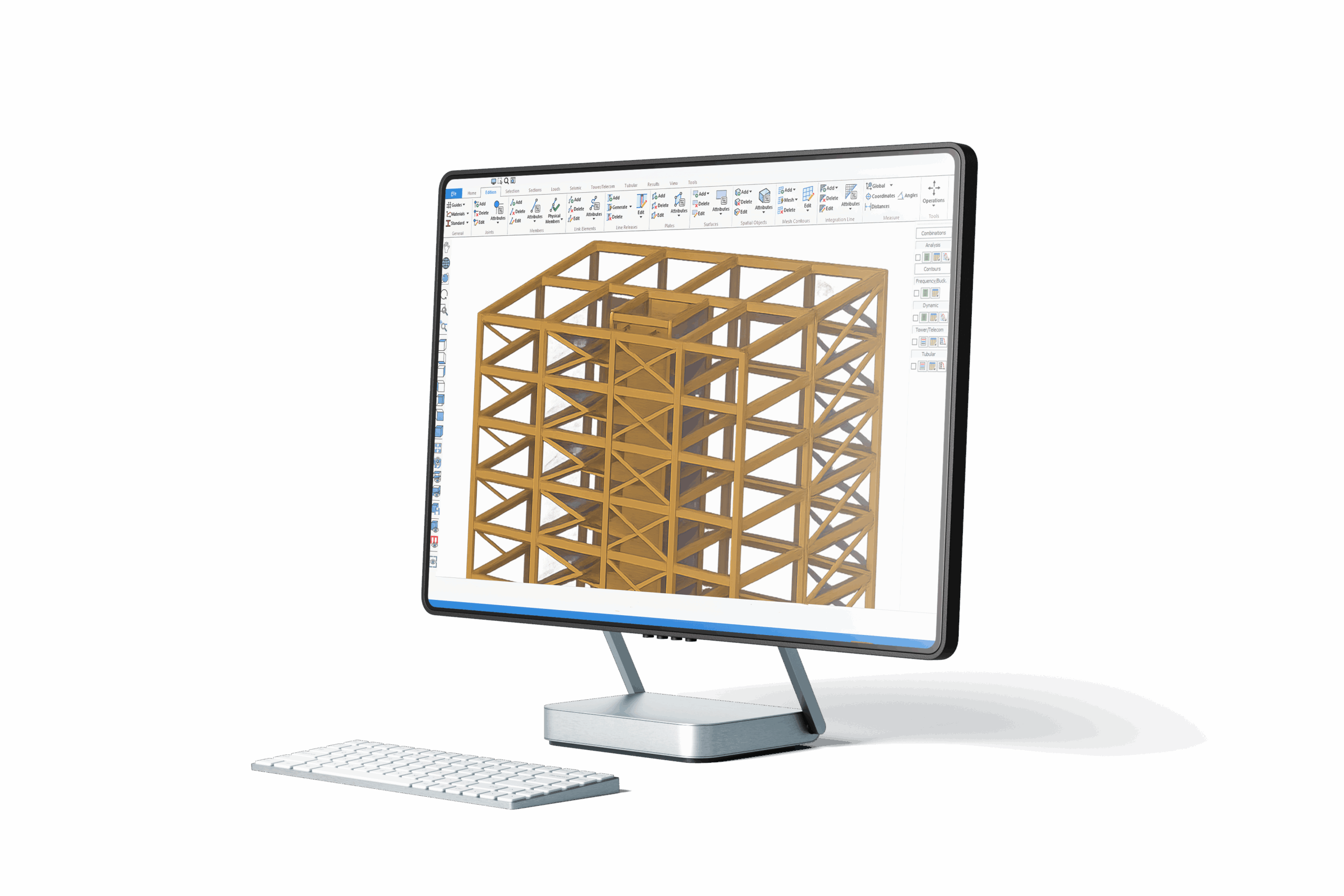
GSE WOOD

GSE - General Structural Engineering

Timber Structural Analysis and Design software

GSE Wood - Advanced Structural Engineering Software

Part of the GSE (General Structural Engineering) software suite, GSE Wood is a specialized module that offers the capability to design and analyze timber structures, including light wood framing and engineered wood structures. It aligns with industry standards such as the 2018 National Design Specification (NDS) for Wood Construction and the CAN/CSA O86-19 standards, ensuring compliance and precision in timber structural engineering.

GSE Wood provides the flexibility to work with two key types of timber structures: beam-column frames and light framing. The Light Framing package extends the Mass Timber features. This addition enhances the software’s ability to automate parametric generation, analysis, and design of bearing walls and shearwalls, streamlining the design process for these critical components.

GSE Wood, with its robust capabilities for timber and engineered wood structural design, empowers engineers to efficiently create and analyze timber-based structures, while maintaining compliance with the latest industry standards. This versatile tool is critical for timber engineering professionals working on a variety of projects.

Fill out the following form to access the GSE Wood demonstration

Optimize your workflow for greater efficiency

Explore the extensive features and functionalities of GSE General Structural Engineering – GSE Wood software. You will discover remarkable capabilities, user-friendly modeling tools, and robust analytical resources that empower you to tackle engineering challenges with enhanced efficiency and precision.

Enhance your workflow with the GSE wood design software

Including Mass Timber and Light Frame Wood

Enjoy unlimited access to the GSE software for 1 year

Overview

Mass Timber Design

Design made according to the NDS National Design Specification (NDS) for Wood Construction and the CSA O86-19.
All parameters required to calculate the resistance of the elements such as unbraced length, buckling lengths, buckling factors, resistance factors and others can be customized either graphically or from spreadsheets.
The program can also calculate several design parameters.
Calculations of bending, compression, tension, shear, bearing and combined resistance of wood elements can be carried on the results of a linear, P-Delta, non-linear, seismic or dynamic analysis.
Complete check of deflection according to a comprehensive set of criterions.
Limit states (unity checks) can be displayed graphically on the 3D model by means of colors or numerically in spreadsheets and reports
All intermediate results required to verify the calculations are provided in spreadsheets.
Notches can be defined at the top and bottom chord for each member end for the purpose of calculating the shear resistance.
The Re-Design command allows to run a partial analysis on selected members. It is possible to modify the section of the members or the material type and properties. The chosen section may then be assigned to the selected members of the model.
Calculation of structural elements like beams, simple or built-up columns, inclined roof purlins, straps, decking, various arcs (circular, parabolic, Tudor, triangular, broken arcs).
Beams and arcs may be straight or curved with a constant or variable section. For curved elements, tension perpendicular to grain needs to be verified manually.
Calculates the ultimate limit states, service limit states and vibration control of wood joists.
Roofs and floors made of plywood or OSB panels can be calculated.
Calculation of wood trusses with metallic connections according to the TPIC.
Vibration of sawn lumber joists
The vibration limit state is calculated for sawn lumber floor joists. To improve the productivity of GSE users, the floor joists are automatically generated inside the truss load surfaces.

Using the automatically generated joists, the resistance and vibration limit states are calculated for each floor. The resistance of sawn lumber joists is verified for the National Design Specification (NDS) and CSA O86 standards. For the vibration limit state, the maximum allowable span is calculated using the NBCC provisions.

Learn more about this feature
Fire resistance of wood elements

The fire resistance of sawn lumber and glulam large cross-section members is calculated for the National Design Specification (NDS) and CSA O86-19 standards.
Sections and grades

• Rectangular sawn lumbers.
• Composite sections such as Laminated Veneer Lumber (LVL), Parallel Strand umber (PSL), Laminated Strand Lumber (LSL).
• Glued-Laminates sections.
• Built-up sections (multiple vertical or horizontal plies of sawn lumbers or composite lumbers) with different anchorage mechanisms.
• Open-web, engineering joists and wood panels.
• Extensive library of common sawn wood sizes available on the market.
• Extensive library of proprietary wood joists, wood panels, composite sections and glulam sections.
• Sections of special dimensions (6 1/4 x 11 3/8 for example) can also be defined and analyzed.
• Guided material selection (automatic material properties) based on section sizes, species and grade.
Resistance factors

• Modification coefficients are determined automatically based on a small number of parameters and selected design code. All coefficients may be defined manually if needed.
• The size coefficients are calculated automatically according to the section sizes.
• The load duration coefficient is determined automatically for each load combination and is applied to the calculation of the wood element’ resistances.
• The support parameters used in the shear and bearing resistance (compression perpendicular to grain) can be specified. These parameters can be different for the two ends of members.
Light frame wood design
Light Framing system is a high-level technology for automated parametric generation, analysis and design of bearing walls and shearwalls.
• Detailed results for each shear-wall segment, including the forces in anchors (Rij) and the shear forces (Vf).
• The shear forces on each segment are calculated according to two methods: Shear force distribution based on the stiffness of the shearwall segments and shear force distribution based on the shear resistance of the segments.
• Design of floor diaphragms.
• Account for nails and anchors in shearwalls stiffnesses and lateral deflections.
• Wall design can be carried on the results of a linear, P-Delta, non-linear, seismic or dynamic analysis.
Parametric model generation

• Create wall outlines by clicking two or three points in the 3D environment.
• The wall surfaces can be rectangular or trapezoidal.
• The wall outlines can be copied to create the structure faces and the different stories of the structure.
• Windows and doors opening can be created and stored in a library to be reused for a series of walls.
• The lintel can be positioned directly above the opening or at the top of the wall.
• The opening members can have their sections assigned according to those of the wall or can be selected manually.
• The wall generator creates the members and loading surfaces of the wall and assigns basic properties and wood design parameters to these elements.
• Engineering model is generated automatically based on the wall, openings, sheathing and anchors parameters.
• All wall elements can be edited, which gives full control to users.
• The walls can either be bearing walls or shearwalls.
• The sheathing parameters and the anchorages configuration can be specified for each wall segment in order to calculate the shear resistance of the shearwall segments.
• Each element in the wall can be made of a simple or built-up wood section chosen by users. Any type of wood section is allowed.
• Studs are automatically positioned in the wall according to the selected spacing.

GSE Timber Design Software

Need more information?

Optimize workflow efficiency and achieve better results using a hybrid solution

The GSE (General Structural Engineering) software provides a powerful and flexible platform for structural engineers to streamline their design workflows and optimize design time.

The ability to run multiple material design simultaneously is a significant advantage offered by the GSE (General Structural Engineering) software. This feature provides structural engineers with enhanced flexibility and efficiency in their design processes. This means that engineers can work with different materials like steel, concrete, wood or aluminum within the same software environment. This flexibility allows for efficient design and analysis of structures that may involve various materials.

By integrating various design and analysis tools, GSE aims to help engineers optimize their design time. This efficiency is critical in today’s fast-paced engineering projects, allowing for quicker turnaround times and cost-effective designs.

GSE steel is a specialized software application integrated within the General Structural Engineering (GSE) software suite. GSE Steel is a powerful and versatile software tool for structural engineers and designers working with steel and composite steel-concrete structures. Its support for various design codes and parametric section shapes, along with its user-friendly interface and optimization capabilities, make it a valuable resource for efficient and accurate structural design and analysis.

GSE Steel supports multiple international design codes, including:

   – American AISC 360 (LRFD and ASD)

   – Canadian CSA 16

  – AISI S100-16 and CSA S136-16

   – European Eurocode 3 and 4

   – Indian IS 800

Learn more about the GSE Steel

The GSE (General Structural Engineering) software includes a powerful suite of tools for integrated structural concrete design, slab engineering, and slab generation.

GSE Concrete is a comprehensive module within the GSE software, enabling the design of concrete members under various conditions, including linear, P-Delta, non-linear, seismic, and dynamic analyses. This feature-rich component ensures precise concrete design for a wide range of structural scenarios.

GSE Concrete offers support for several international building codes, including the American ACI-318, the Canadian CSA-A23.3, and the Egyptian code ECCS 203. This ensures compliance with regional standards and regulations for concrete structural design.

The GSE Concrete software suite, with its comprehensive concrete design, slab engineering, and slab generation capabilities, empowers engineers to tackle diverse concrete-related projects efficiently and accurately, meeting industry standards and codes.

Learn more about the GSE Concrete

Within the GSE (General Structural Engineering) software suite, GSE Wood is a specialized module that offers the capability to design and analyze timber structures, including light wood framing and engineered wood structures. It aligns with industry standards such as the 2018 National Design Specification (NDS) for Wood Construction and the CAN/CSA O86-19 standards, ensuring compliance and precision in timber structural engineering.

GSE Wood provides the flexibility to work with two key types of timber structures: beam-column frames and light framing. The Light Framing package extends the Mass Timber features. This addition enhances the software’s ability to automate parametric generation, analysis, and design of bearing walls and shearwalls, streamlining the design process for these critical components.

GSE Wood, with its robust capabilities for timber and engineered wood structural design, empowers engineers to efficiently create and analyze timber-based structures, while maintaining compliance with the latest industry standards. This versatile tool is critical for timber engineering professionals working on a variety of projects.

Learn more about the GSE Wood

GSE Aluminum is a specialized software application integrated within the GSE (General Structural Engineering) software suite used for the design and verification of aluminum structures of various types.

GSE Aluminum supports industry-standard design codes, including:

– GSE Aluminum complies with the 2020 Edition of the Aluminum Design Manual published by the Aluminum Association (AA ADM-2020)

– The software also adheres to the CAN/CSA S157 design code

Learn more about the GSE Aluminum

GSE - 1 year software subscription

Enjoy unlimited access to your software for 1 year

GSE Quote request

General Structural Engineering Software

Thank you for downloading your free demo of the GSE Wood - Advanced Structural Engineering Software.

Request more information

Complete this form if you would like to receive more information regarding the GSE Wood Software.