0

SAFI™ Telecom software

ANSI/TIA-222 CSA S37-24

The industry-standard software for telecom tower design &

structural compliance.

Structural analysis and design of lattice towers, monopoles and guyed masts — fully compliant with ANSI/TIA-222 and CSA S37. Trusted by the world's leading engineering firms for over 40 years.

Telecom Towers Structural Analysis and Design (ANSI/TIA-222-I and CSA S37-24)

SAFI™ Telecom Software

Structural analysis and design of steel telecommunication structures, including self-supporting lattice towers, monopole towers, and guyed masts, seamlessly aligning to the ANSI/TIA-222 and CSA S37 standards.

Trusted by the world's leading engineering firms for over 40 years

Engineered for productivity.
Built exclusively for telecom structural engineers.

SAFI™ Telecom is built specifically for telecom tower designself-supporting lattice towers, monopoles and guyed masts.

Automatic load generation - Built for telecom infrastructures

Automatically calculate wind, ice, dead, and thermal loads for every member, dish, and antenna – with built-in US county and Canadian province databases supporting TIA-222-I and CSA S37-24.

Comprehensive tower analysis - with animated results

Advanced structural analysis workflows with animated results, FEA, P-Delta, nonlinear, buckling, seismic time-history, and more — with support for non-structural components.

Parametric telecom modeling - Built for productivity

Parametric generators and panel libraries let you build complete latticed tower, monopole or guyed mast models efficiently – with full 3D model including antennas, dishes and feedlines.

SAFI™ Telecom software

free webinar

A productive software built for telecom structural engineers.

SAFI™ Telecom – Explore the full telecom tower design workflow in a short technical walkthrough.

Register today to receive your free webinar directly in your inbox.

Core features of SAFI™ Telecom software

A structural analysis and design software for professional telecommunication engineers.

Load generation in compliance with TIA-222 & CSA S37

•  Automatic calculation of wind and ice loads on members, dishes, antennas, and feedlines.

• Automatic generations of dead, wind, ice, thermal loads cases and load combinations.
•  Uniform wind pressure profile and uniform thickness ice profile.
•  User-defined wind pressure profiles.
• United States county listings of design criteria for wind, wind with ice, and ice.

• Databases of wind, ice, and spectral accelerations for specified states, counties and provinces in the United States and Canada.
• Loading for joints, members including concentrated, uniform, trapezoidal and thermal loads.
• Loading for surfaces and finite element plates.
• Automatic calculation of drag coefficients, gust factors, topographic parameters and escalate ice thickness according to TIA-222.
• Display loads graphically and detailed wind and ice loads parameters can be displayed in numerical tables.

Telecom Towers Structural Analysis and Design (ANSI/TIA-222-I and CSA S37-24)

Robust and comprehensive structural analysis

Telecom software features comprehensive state-of-the-art structural analysis methods, including:
• Finite Elements Analysis (FEA) including plates and shell elements
• P-Delta Analysis, Linear and Nonlinear Analysis, Buckling Analysis
• Static Equivalent Seismic Analysis, Seismic and Dynamic Time-History Analysis
• Non-linear analysis using load control and displacement control strategy
• Linear and exact non-linear cable elements
• Direct Analysis Method (DAM) and the Effective Length Method (kL) for AISC 360
• Possibility to add non-structural components using Spatial Objects and Spatial Loads to automatically calculate dead, ice, and wind loads

Parametric lattice tower generation

Build complete lattice tower models with automated 3D generation and integrated engineering libraries.

• Full 3D modeling of structural and mounted components
• Parametric workflows for rapid tower generation
• Integrated libraries for panels, materials, sections, and attachments
• Custom panel creation with the panel editor
• Support for discrete or linear attachments such as antennas, dishes, feedlines, guys, and transmission wires, diagonals, diaphragms.

Telecom Towers Structural Analysis and Design (ANSI/TIA-222-I and CSA S37-24)

Automated telecom towers, masts, and monopoles generation

• Automatic generation of 3-sided and 4-sided lattice towers, guyed masts, and monopoles
• Automatic feedline generation for lattice tower structures
• Built-in databases for cables, dishes, antennas, and transmission wires
• Extensive panel libraries and parametric modeling workflows
• Powerful load generator wizard and automated wind and ice load generation
• Integrated analysis, design checks, and structural visualization tools

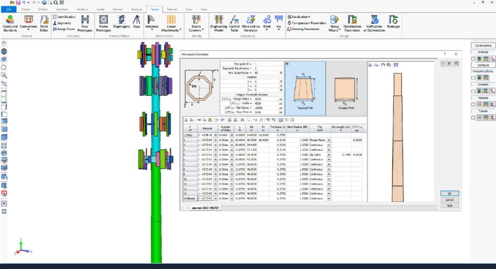
Monopole generation with fatigue analysis

Generate tapered and stepped monopole structures using parametric workflows and integrated fatigue analysis tools.
• Automatic monopole generation from key dimensions and parameters
• Support for tapered and stepped monopole configurations
• Real-time, to-scale structural previews
• Automatic subdivision of physical members
• Fatigue threshold definition for joints and base plates
• Integrated fatigue load calculation workflows
Telecom Towers Structural Analysis and Design (ANSI/TIA-222-I and CSA S37-24)
SAFI Structural Analysis software Results Animation

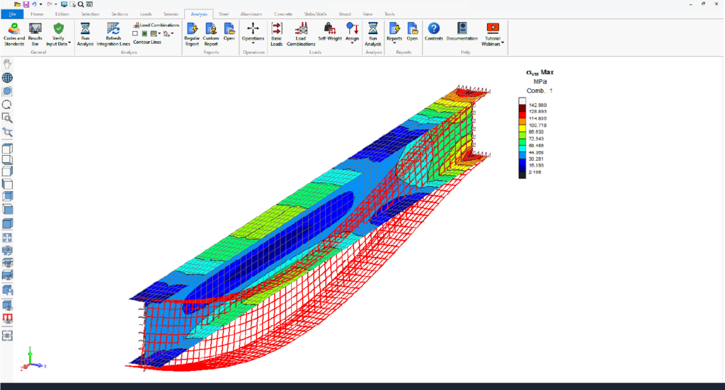
Structural insights animation

SAFI™ Telecom software allows users to animate analysis results, including static, P-Delta, buckling, seismic, and dynamic analyses. This visualization highlights displacements, internal forces, stresses, reactions, mode shapes, and time-history data, offering clear insights into structural behavior.

Animating envelopes focuses on critical regions, simplifying complex data for better decision-making during dynamic events.

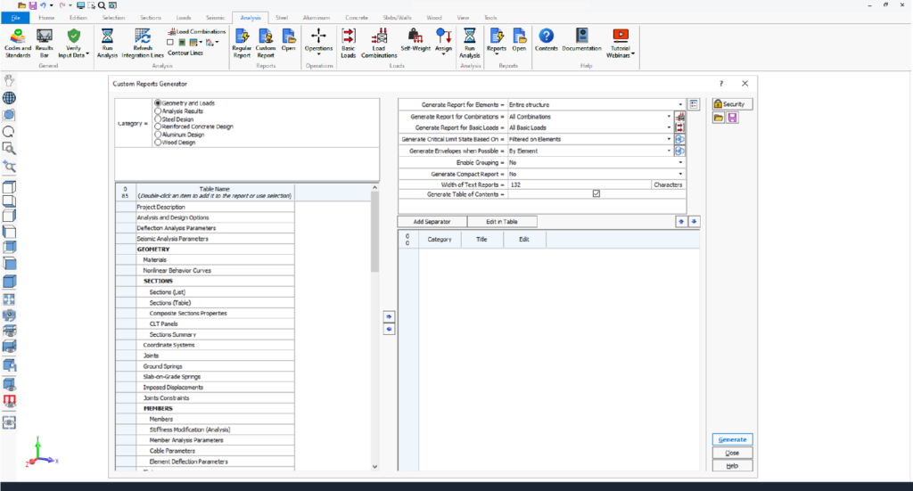
Executive custom reporting - editable professional reports

SAFI™ Telecom software offers advanced custom reporting tools, enabling users to create tailored, professional reports with ease. With options to select relevant data, add individual or multiple tables, and customize settings, users can design layouts that meet specific project needs.

Editable titles, table reordering, and predefined templates enhance efficiency, while saved custom layouts streamline future reporting. Reports can be customized and exported to Microsoft Word and Excel, streamlining workflows.

SAFI Structural Analysis software Custom Reports
Telecom Towers Structural Analysis and Design (ANSI/TIA-222-I and CSA S37-24)

Intuitive graphical ribbon-based interface

SAFI™ Telecom software features an intuitive, ribbon-based graphical user interface powered by DirectX 11 and OpenGL 2.0 for enhanced performance. Users can efficiently create, analyze, and design complex models, visualized as lines, wireframes, or 3D solids.

Users benefit from key functionalities such as detailed element creation, and transparency options for components like members, plates, surfaces, spatial objects and panels.

Additionally, powerful edition features allow to model very complex and non-standards towers. The software supports metric, imperial, and mixed unit systems, which can be modified at any time. 

Streamlined modeling with Telecom's advanced tools

SAFI™ Telecom software provides powerful and efficient tools for creating diverse latticed structure models. Engineers can streamline their modeling process with the parametric wizard generator and extensive panel libraries. The automatic model generator creates complete 3D tower models, including main members, diagonals, diaphragms, and rigid connections.

Users can customize panels with the intuitive Panel Editor or choose from a robust library of standard panel designs. Furthermore, the standard libraries offer a wide selection of materials and sections, enhancing convenience and flexibility.

Telecom Towers Structural Analysis and Design (ANSI/TIA-222-I and CSA S37-24)
SAFI Structural Analysis software Custom Reports

Comprehensive results visualization

Results and input data can be visualized, printed, and exported with flexible options for customization, reporting formats, and graphics sharing.
• Visualize results graphically or numerically.
• Print input data and results for the entire structure or specific parts using graphical selection or element ranges.
• Customize lists of input data and results for printing.
• Reports available in multiple formats: SAFI™ reports, Excel, Access, and ASCII text files.
• Graphics can be printed or copied to the clipboard for use in other programs.

Need more information? Contact us.

A structural analysis software for professional engineers.

Key Features - SAFI™ Telecom Software
Supported design codes

• Telecommunications Industry Association (TIA)-222-I
• Telecommunications Industry Association (TIA)-222-H
• Telecommunications Industry Association (TIA)-222-G
• Canadian Standards Association CSA S37-24
• Canadian Standards Association CSA S37-18

Structural Analysis

Automatic generation of dead, ice, thermal and wind loads according to TIA-222 and CSA S37.
Uniform wind pressure profile and uniform thickness ice profile.
User-defined wind pressure profiles.
United States county listings of design criteria for wind, wind with ice, and ice.
Loading for joints, members including concentrated, uniform, trapezoidal and thermal loads.
Loading for surfaces and finite element plates.
Automatic calculation of drag coefficients, gust factors, topographic parameters and escalate ice thickness according to TIA-222.
Display loads graphically and detailed wind and ice loads parameters can be displayed in numerical tables.

Comprehensive Analysis methods including:
– Static linear
– P-Delta
– Static non-linear
– Buckling
– Natural frequencies
– Seismic and dynamic

Linear and exact nonlinear cable elements (catenary cables).
Automatic handling of tension-only members.

Dynamic Fatigue and Loads

Tower dynamic effect and fatigue according to S37 Annex N.
Automatic generation of fatigue wind gust loads and vortex shedding loading according to the TIA-222 and CSA S37.
Design checks according to TIA-222-I, TIA-222-H, TIA-222-G, and CSA S37-24, CSA S37-18.

Design checks of the following sections:
Rolled 90° and 60° (schifflerized) angles
60° and 90° cold formed angles
HSS and pipes
Round sections
Tubular sections (8 sides, 12 sides, 16 sides, 18 sides, 20 sides, 24 sides, and round)

Fatigue parameters

The Monopole Generator command auto assign the fatigue parameter when generating the model according to the input data. If the model has been created manually or after the model automatic generation is done, users can edit the Fatigue Parameters table to change the fatigue parameters for the connection details for both ends of the member or it can be edited graphically (see Member Attributes – Tubular).

Automatic calculation of wind and ice loads

• Automatically generates wind, ice, dead, and thermal loads
• Compliant with

TIA-222-H / G / I and

CSA S37-18 /24 standards


• All design and geometric parameters are auto-calculated (slenderness ratios, force coefficients, etc.)


Wind and ice loads generator
• Automatically generate wind and ice loads on open structures

• Supports multiple load conditions based on selected distribution:
– Wind only
– Wind with ice
– Service wind load
– Two thermal load
– Self-weight load
– Ice load

Wind loads
• Define wind load parameters using the Wind Loads command
• SAFI Telecom Software automatically distributes wind loads across the structure
• Loads are generated automatically during analysis

• View generated wind data anytime with the Wind Load Data command

Telecom design features

Available design provisions include ANSI/TIA-222 and CSA S37.

Members are checked against their ultimate strength in accordance with the selected code.
Design checks include:
– Slenderness ratios
– Buckling length
– Tension
– Compression
– Connections (shear, bearing, block shear)
– Anchor rods

Calculation of the equivalent loads on footings.

Can optionally check members according to LRFD for:
– Bending
– Tension-bending
– Compression-bending
– Shear
– Torsion
– Warping

Profile optimization of selected members allows to test different section shapes, grade and material types.

Antennas

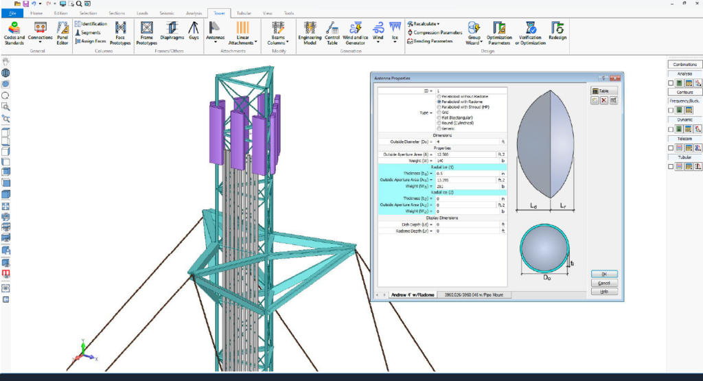
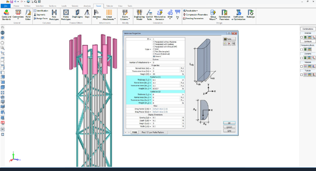
The Antennas command allows to define telecommunication antenna properties.

Various types of antennas are possible such as:
Dish
– Paraboloid without Radome
– Paraboloid with Radome
– Paraboloid with Shroud (HP)
Grid
Flat
Round

Definition of bolts

Users can use the definition of bolts command to define the layout and properties of the bolts that will be used to connect the members of the structure.

Diameter (D)
Threads Pitch (tp)
Tensile Stress (Fub)
Shear Strength (Through Body) (Fvb)
Shear Strength (Through Threads) (Fvt)

Connection schemas

The Connection Schema command allows users to define the layout and properties of the bolts used to connect structural members, including:

Bolt properties:
• Bolt type
• Diameter (D)
• Thread pitch (tp)
• Ultimate stress (Fu)
• Bolt class

Type of connection:
• Direct connections
• Splice connections

Additional configurable parameters:
• Number of bolted flanges
• Number of bolt columns

Telecom specifications

Column face prototypes
A column is composed of several segments placed in a sequential order. Each column face is made of panels which fit into the column segments.

The Column Face Prototypes dialog box is used to define this sequence of panels. Each sequence is defined independently from the column; it will be attached to a specific column face by the Column Face Identification command.

Frame prototypes
The library in which the panel is defined as well as the desired panel must be selected in the Panel Library and Panel Name lists.

The Telecom Software provides a series of standard connection and diaphragm panels which can be found in the Standard-D library. Additional panels can also be created using the Panel Editor.

Guys
The Guys command allows to define the guys configuration for guyed towers. The guys and attachment members are generated when the tower model is generated using the Generation of Model command.

Anchor rods and Base plates
The anchor rods command is used to define the parameters of the anchorage of the columns to the foundations. Four types of anchors are available.

Anchors rods are checked for fatigue loading. New parameters in the Anchor Rods and Base Plates dialog box are available to define the fatigue threshold for the anchor rod. The fatigue check results are available in the anchor rods design table for fatigue load combinations.

ASCE 48-11 method
TIA-222-H method (Annex Q)

Vortex Shedding Force Calculator
This command helps users to quickly calculate the vortex shedding distributed force (Fvs) according to the Annex N of the S37-18.

Load generation

Telecom Software has capabilities to manually add joint and member loads as well as for the automatic generation of code-specified loads.

Surface wind loads data
The surface wind loads may be filtered before being displayed. It is possible to restrain the displayed results to the selected surfaces or to display them for the entire model. It is also possible to display the results for a specific basic load.

Ice loads
The Ice Loads command is used to define the tower ice loads parameters.  Telecom Software automatically generates the distribution of the ice loads on the structure according to these parameters.

The generation of the loads is made automatically during the analysis. However, the user may view the generated data with the Ice Load Data command prior to running the analysis.

Member ice loads
The member ice loads may be filtered before being displayed. It is possible to restrain the displayed results to the selected members or to display them for the entire model. It is also possible to display the results for a specific basic load.

Member wind loads data
The member wind loads may be filtered before being displayed. It is possible to restrain the displayed results to the selected elements or to display them for the entire model. It is also possible to display the results for a specific basic load.

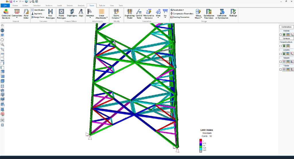
Limit states

• Displayed graphically on the 3D model through color representation or presented numerically in spreadsheets and reports

Discover why professional engineers are choosing SAFI™ Telecom Software.

Intuitive software to model, analyze, and design steel telecommunication structures such as self-supporting towers, guyed masts, and monopoles.

Ready to get started? Contact us today to explore SAFI™ Telecom software.