- Structural Analysis Features
Torsion and warping
TECHNICAL FEATURE // TORSION AND WARPING

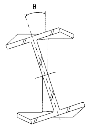
In addition to shear stresses, some members carry torque by axial stresses. This is called warping torsion. This happens when the cross-section wants to warp, i.e., displace axially, but is prevented from doing so during twisting of the beam. In other words, the section tends to resist torsion by out of plane bending of the flanges.
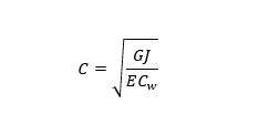
For solid and thin-wall closed sections (square, rectangular and circular tubes) these effects are often negligible. However, for thin-wall open sections restrained warping is often dominant. To include the effect of restrained warping we need to know the torsion constant J and the warping constant Cw which are geometric properties of the cross-section. For open shapes (I, C, Z, T, L, built-up …) the following equation may be used to evaluate the influence of the warping.

G Shear modulus of elasticity of the material
J Torsional constant for the cross section
E Modulus of elasticity of the material
Cw Warping constant for the cross-section
For axisymmetric cross-sections and thin-walled cross-sections with straight parts that intersect at one point such as X-shaped, T-shaped, and L-shaped cross-sections pure torsion will generally dominate over warping stresses. In these cases, torsional loads are carried by pure torsional shear stresses (St-Venant torsion) regardless of the boundary conditions.
Subscribe to our technical newsletter
Related Posts

NCSEA Structural Engineering Summit 2024
We’re thrilled to announce our participation as an exhibitor at the upcoming NCSEA 2024 Structural Engineering Summit. Join us at Booth #610.

Variable anchorage slip in wood shearwalls
To enhance productivity of GSE Timber software’ users, the Anchorage Elongation Method can be defined as variable (tension only) and variable (tension and compression). The anchorage slip is calculated at each iteration according to the tension efforts at the anchorage locations.
Fatigue limit state
HSE users can efficiently set and edit all required fatigue parameters for the structure allowing to consider all applicable fatigue loads such as Galloping, Natural Wind Gust, or Truck-Induced Gust.
Live load reduction
The live load reduction is available for the GSE steel, concrete, aluminum, and wood modules. The live load reduction will be applied to the columns of the structure.
Live loads can be automatically reduced according to the selected method. The software computes the live load reduction factor (LLRF) that will reduce the effective axial compression force in columns.
