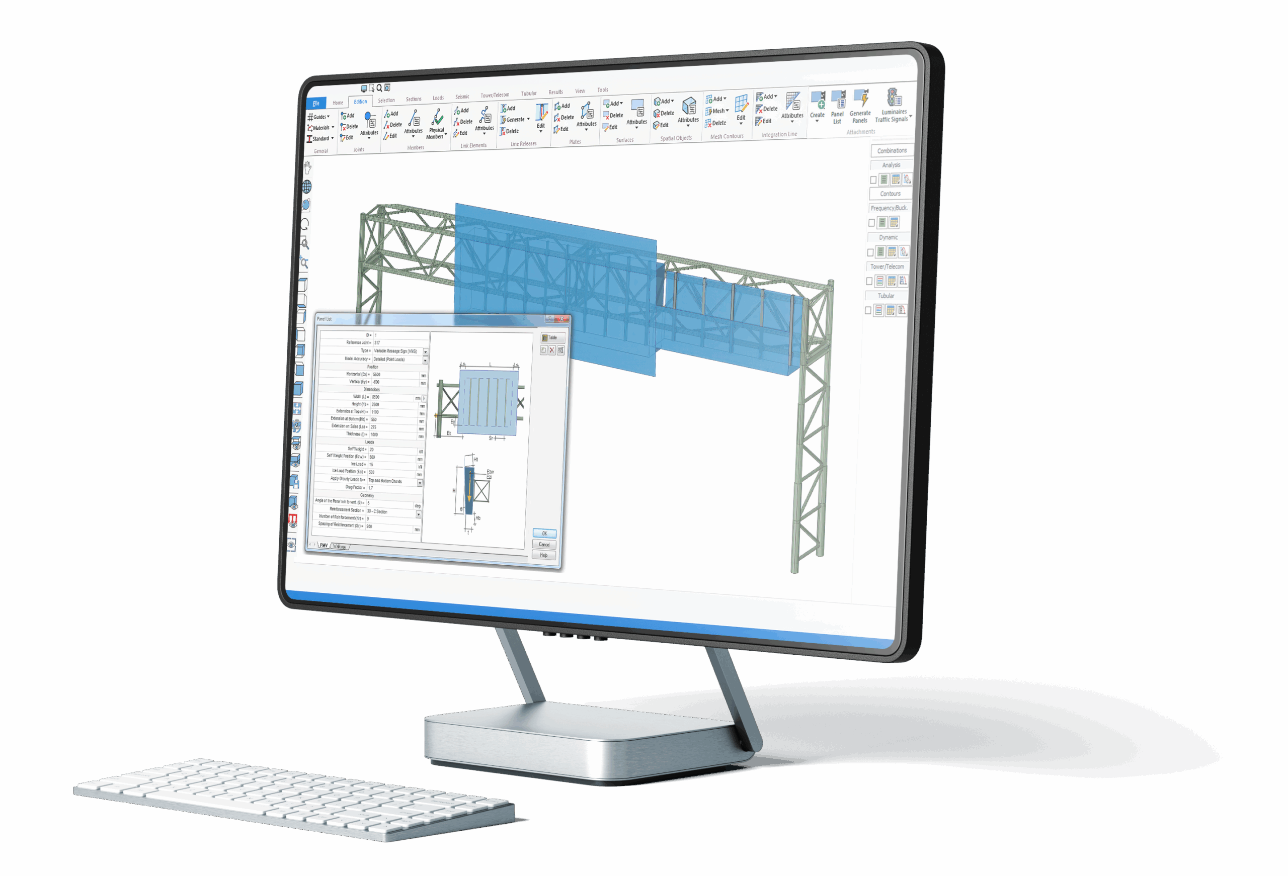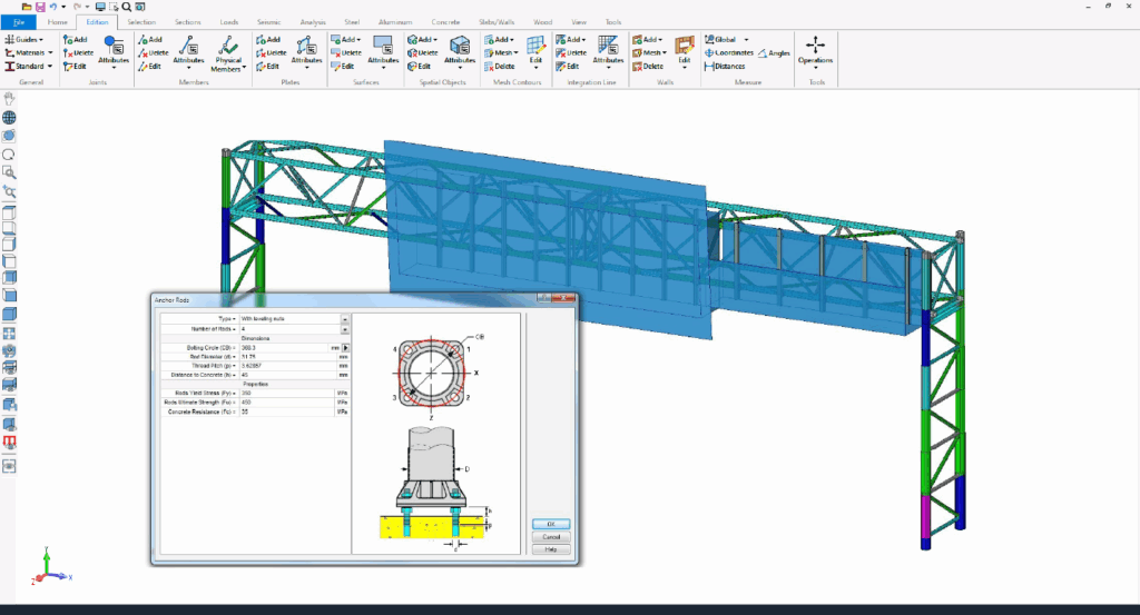
Highway Sign, Traffic Signal & HMLT Structural Analysis, Design & Evaluation Software
HSE™ Structural Analysis Software
AASHTO LTS-13 ASD (6th edition)
AASHTO LTS-15 LRFD (1st edition)
CAN/CSA S6
The industry-leading software for highway sign structures design &
structural compliance.
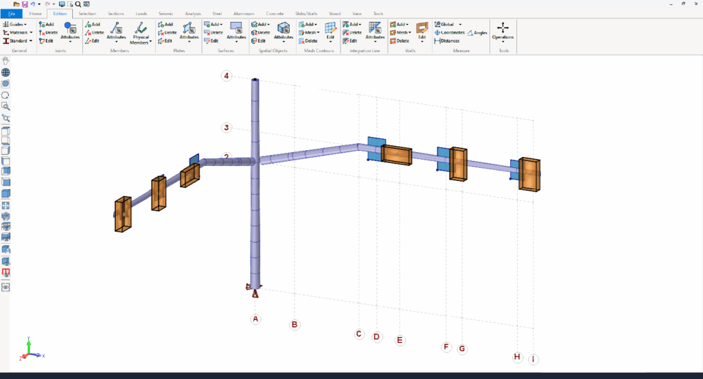
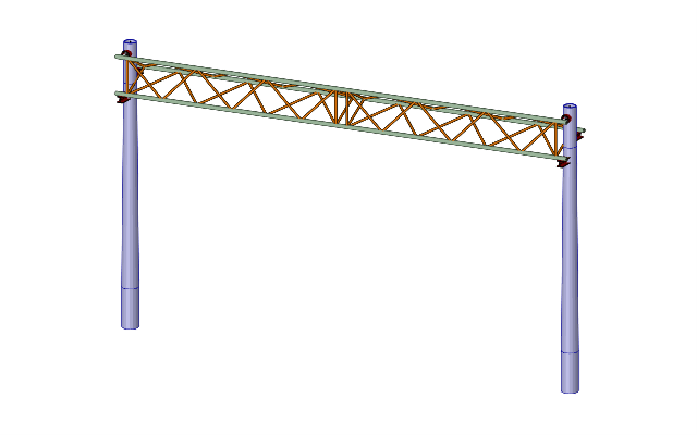
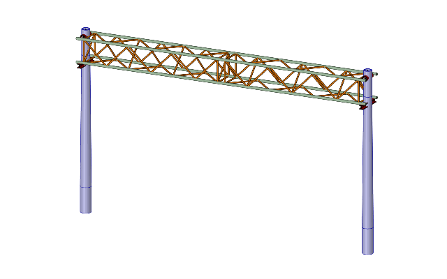
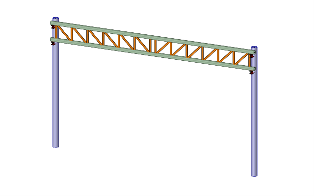
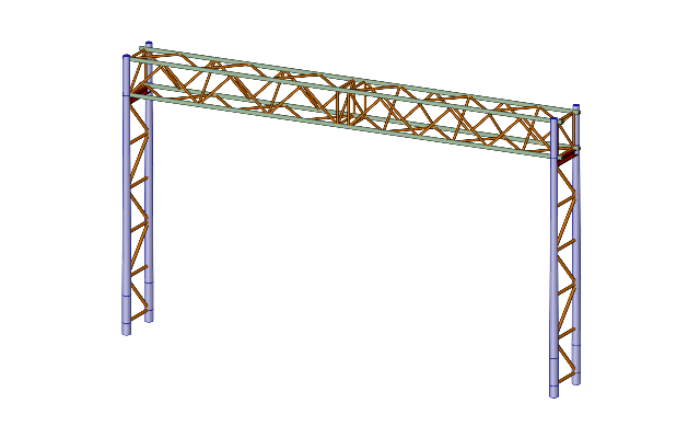
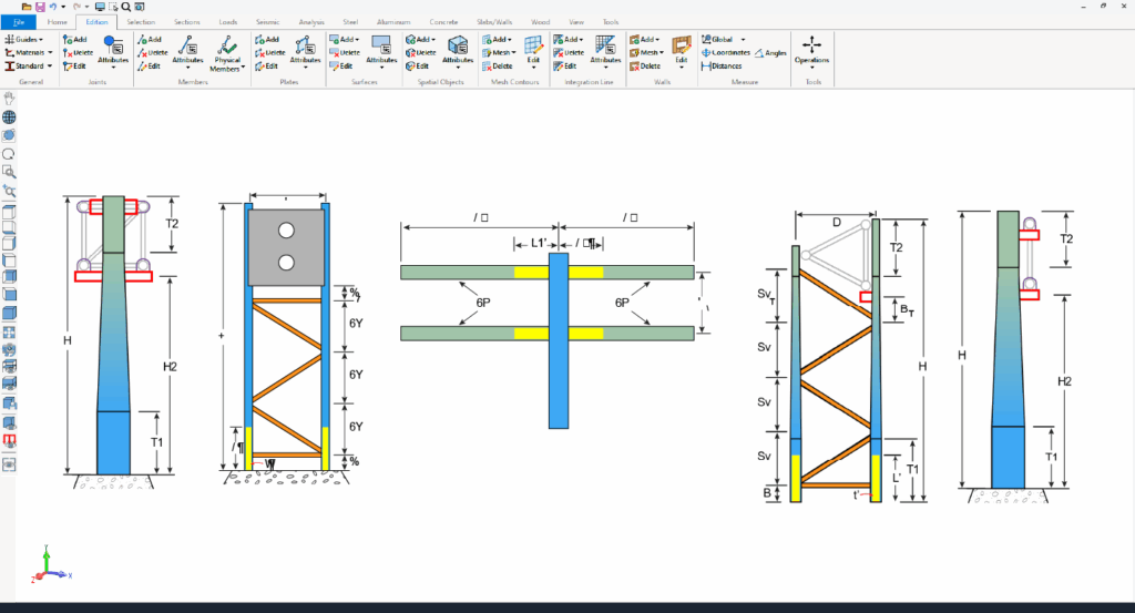
Structural analysis and design of Overhead Sign Structures, Traffic Signal Supports, and High-Mast Lighting Towers HMLT — fully compliant with AASHTO LTS-13 ASD (6th edition), AASHTO LTS-15 LRFD (1st edition) and CAN/CSA S6.