TECHNICAL FEATURE // SECTION PROPERTIES ACCORDING TO STRAIGHT AXES
ADDITIONAL SECTION PROPERTIES AVAILABLE
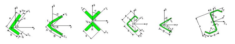
When the alpha angle for a section is different than zero, it means that the principal axes does not correspond to the straight axes. The images below show some of these sections:
To get the exact analysis results, the sections must be analyzed on their principal axes. The bending resistance must also be computed on the principal axes of the section.
It is now possible to see the section properties on the straight axes by clicking on the Additional Properties button. The properties on the straight axes are provided for information only since they are not directly used by the software.
DEFLECTIONS AVAILABLE ON STRAIGHT AXES
In the previous version of the software, the internal displacements of the member were always displayed according to the principal axes of the section. In addition, it is now possible to display the deflections on the straight axes.
For example, for a simply supported single angle with vertical loads the displacement is not only vertical. A horizontal component to the deflection is also computed, as displayed below.
Also, the deflection criteria and the limit states calculation for the deflections with an alpha angle different than zero are now done on the straight axes.
SHEAR FORCES AND BENDING MOMENTS AVAILABLE ON STRAIGHT AXES
In the previous version of the software, the internal forces for the members were always displayed according to the principal axes of the section.
It is now possible to display shear forces and bending moments on the straight axes. This can be done using the graphic visualization command of the Internal Member Forces.
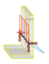
The forces and moments on the straight axes can also be visualized on the structure in the main window. For example, for a simply supported single angle with vertical loads, the moments on the strong and weak axes are both different than zero, as displayed below. Note that the steel design for bending moments are always done according to the principal axes.
3D multi-material analysis and design software for CLT, Mass Timber, Light-Frame Wood, Steel, Cold-Formed Steel, Reinforced Concrete, Automated Slab and Foundation design, and Aluminum.