- GSE Features
Vibration of sawn lumber joists
TECHNICAL FEATURE // GSE SOFTWARE: Vibration of sawn lumber joists
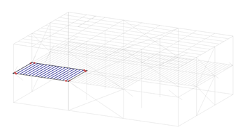
Using the automatically generated joists, the resistance and vibration limit states are calculated for each floor. The resistance of sawn lumber joists are verified for the CSA O86 and National Design Specification (NDS) standards. For the vibration limit state, the maximum allowable span is calculated using the NBCC provisions.
With this function, users can generate and efficiently verify and design sawn lumber joists.

To simplify the user inputs, the sawn wood members design parameters have been automatically applied and simplified in accordance with floor typical uses. Hence, the floor ultimate limit states are quickly calculated. The bending, shear, bearing and deflection limit states are calculated.
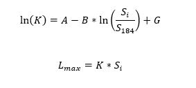
As per the NBCC, the vibration service limit state of floors are determined by their spans. The NBCC provides a set of equations to calculate the maximum allowable span for the joists. The main equations are presented below:


GSE Software
The General Structural Engineering (GSE) software is a fully integrated analysis and design software for structural engineering. The software accounts for steel, cold-formed steel, concrete, automated slab design, timber, light frame wood and aluminum.
Related Posts

IEEE PES Conference 2026
We’re thrilled to announce our participation as an exhibitor at the IEEE PES T&P Conference 2026, organized by the Power & Energy Society. Join us at Booth #3587 as we showcase the groundbreaking Virtual Tower Structures® (VTS) software.

NCSEA Structural Engineering Summit 2025
We’re excited to exhibit once again at the NCSEA Structural Engineering Summit! The 2025 edition will take place in New York City, and as returning participants, we’re proud to continue engaging with the community and showcasing tools that advance structural engineering! Join us at Booth #112.

Electrical Transmission and Substation Structures Conference 2025
We’re thrilled to announce our participation as an exhibitor at the Electrical Transmission & Substation Structures (ETS) Conference 2025, organized by the American Society of Civil Engineers ASCE! Join us at Booth #815 as we showcase the groundbreaking Virtual Tower Structures® (VTS) software.

NCSEA Structural Engineering Summit 2024
We’re thrilled to announce our participation as an exhibitor at the upcoming NCSEA 2024 Structural Engineering Summit. Join us at Booth #610.


