

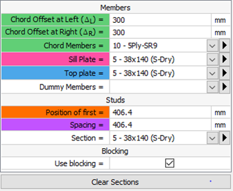
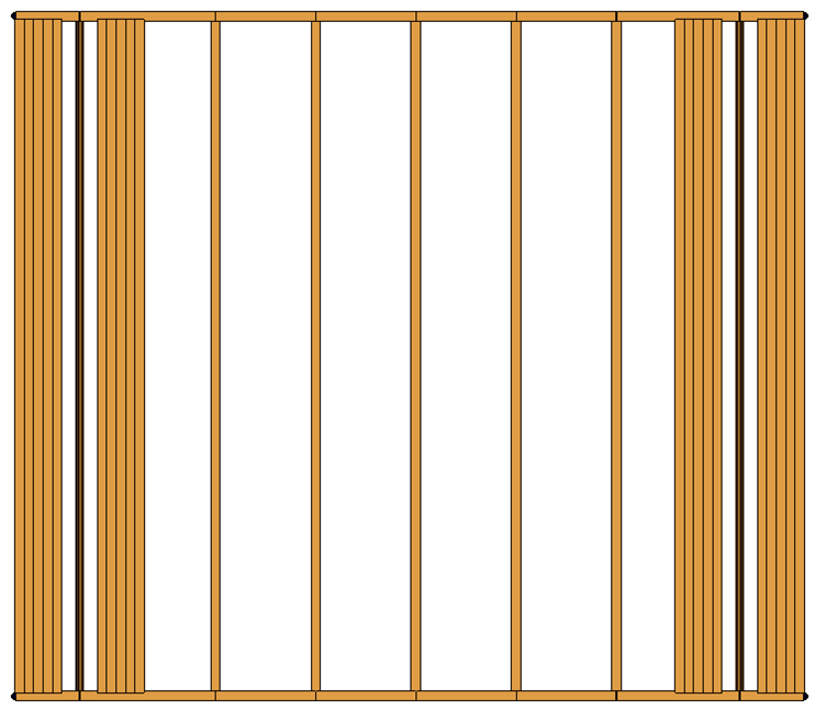
In the GSE Timber software, the wood shearwalls are automatically generated according to the various inputs defined by users in the Wood shearwalls menu. In that menu, the chord members sections are defined.
In previous versions of the GSE, only regular wood sections were available. Now, a new type of section may be created and selected. The new cross-section is composed of two main components, the wood members and a steel rod. The wood members may be built-up sections made of regular sawn lumber.
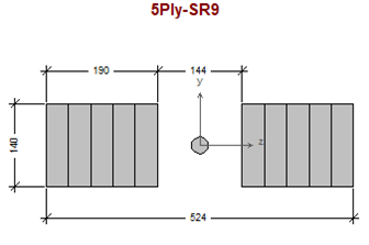

Shearwalls are specifically used to resist lateral loads. Under a lateral loading case, the chord members will resist the tension and compression forces generated by the overturning bending moment. The wood members act as compression only members and the steel rods act as a tension only members. As the tension chord and compression chord are not symmetric, the transformed moment of inertia of the shearwall has to be calculated (Newfield, 2013)1. The steel rod area is calculated as an equivalent wood section.
Itr = At,tr *
ytr2 + Ac *
(Lc - ytr )2
The calculated transformed inertia directly affects the shearwall stiffness and thus, the calculated deflections. The modified wall properties are automatically calculated in the software.
1. Newfield, G., Ni, C., Wang, Wang, J. 2013. A mechanics-based approach for determining deflections of stacked multi-storey wood-based shearwalls. FPInnovations, Vancouver, B.C and Canadian Wood Council, Ottawa, Ont.


IEEE PES Conference 2026
We’re thrilled to announce our participation as an exhibitor at the IEEE PES T&P Conference 2026, organized by the Power & Energy Society. Join us at Booth #3587 as we showcase the groundbreaking Virtual Tower Structures® (VTS) software.
NCSEA Structural Engineering Summit 2025
We’re excited to exhibit once again at the NCSEA Structural Engineering Summit! The 2025 edition will take place in New York City, and as returning participants, we’re proud to continue engaging with the community and showcasing tools that advance structural engineering! Join us at Booth #112.
Electrical Transmission and Substation Structures Conference 2025
We’re thrilled to announce our participation as an exhibitor at the Electrical Transmission & Substation Structures (ETS) Conference 2025, organized by the American Society of Civil Engineers ASCE! Join us at Booth #815 as we showcase the groundbreaking Virtual Tower Structures® (VTS) software.
NCSEA Structural Engineering Summit 2024
We’re thrilled to announce our participation as an exhibitor at the upcoming NCSEA 2024 Structural Engineering Summit. Join us at Booth #610.